Firmware Upgrade — Category Extension Specification
Category ID: 0x1
Extends: can-protocol.md
Version: 1.0
Status: Draft
Date: 2026
1. Overview
This document specifies the Firmware Upgrade category extension for the can-lite protocol. It defines a block-transfer protocol for sending firmware images from a client to a server over CAN, with integrity verification and activation control.
The category does not require protocol-level
sequence validation (RequiresSequenceValidation() = false).
Ordering is enforced by explicit block indices within the data transfer
messages, and the protocol-level 8-bit sequence counter would wrap too
quickly for large transfers (thousands of blocks).
1.1 Design Goals
- Reliability: Per-block acknowledgement and CRC32 verification before activation.
- Resumability: Block-indexed transfer allows the client to detect and retransmit missing blocks.
- Safety: New firmware is verified in-place before activation; the running firmware is never overwritten in-flight.
- Simplicity: No multi-frame segmentation; each CAN frame is self-contained.
1.2 Assumptions
- The server has a dual-bank (A/B) flash layout or a dedicated staging area where incoming firmware is written without overwriting the active image.
- The server’s bootloader or application can swap to the newly written image upon activation.
- Maximum firmware size per transfer: 393 216 bytes (65 536 blocks × 6 data bytes). For larger images, a page-based extension can be added in a future revision.
2. Upgrade States
| Value | State | Description |
|---|---|---|
| 0 | Idle | No upgrade in progress |
| 1 | Receiving | Accepting data blocks |
| 2 | Verifying | CRC32 check in progress |
| 3 | Complete | Verification passed, ready to activate |
| 4 | Error | Transfer or verification failed |
3. Error Codes
| Value | Error | Description |
|---|---|---|
| 0 | Ok | No error |
| 1 | Busy | Upgrade already in progress |
| 2 | InvalidSize | Firmware size exceeds available storage |
| 3 | SequenceError | Block index out of order or duplicate |
| 4 | WriteError | Flash write/erase failure |
| 5 | CrcMismatch | CRC32 verification failed |
| 6 | NotReady | Activate requested before verify passed |
| 7 | InvalidState | Command not valid in current upgrade state |
| 8 | SessionTimeout | No activity within the session timeout |
4. Message Types — Commands (Client → Server)
All commands are sent at CanPriority::command.
4.1 Begin Upgrade (0x00)
Initiate a firmware upgrade session. If an upgrade is already in
progress, the server responds with error code Busy.
| Byte | Field | Type | Description |
|---|---|---|---|
| 0–3 | FirmwareSize | uint32 | Total firmware image size in bytes |
Total: 4 bytes.
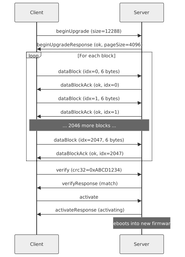
The server erases the staging area (if applicable), transitions to Receiving state, and responds with a Begin Upgrade Response (0x80).
4.2 Data Block (0x01)
Transfer a block of firmware data.
| Byte | Field | Type | Description |
|---|---|---|---|
| 0–1 | BlockIndex | uint16 | Zero-based block sequence number |
| 2–7 | Data | uint8[6] | Firmware data (up to 6 bytes) |
Total: 2–8 bytes. The last block may contain fewer than 6 data bytes.
Blocks must be sent in ascending order starting from 0. The server responds with a Data Block Ack (0x81) for each received block.
4.3 Verify (0x02)
Request CRC32 verification of the received firmware image against the expected checksum.
| Byte | Field | Type | Description |
|---|---|---|---|
| 0–3 | CRC32 | uint32 | Expected CRC32 of the complete firmware |
Total: 4 bytes.
The server transitions to Verifying state, computes the CRC32 over the received data, and responds with a Verify Response (0x82).
4.4 Activate (0x03)
Instruct the server to switch to the newly uploaded firmware. This command is only valid after a successful Verify (state = Complete).
Empty payload.
The server responds with an Activate Response (0x83), then performs the bank swap or reboot. The server may go offline briefly during this process.
4.5 Abort (0x04)
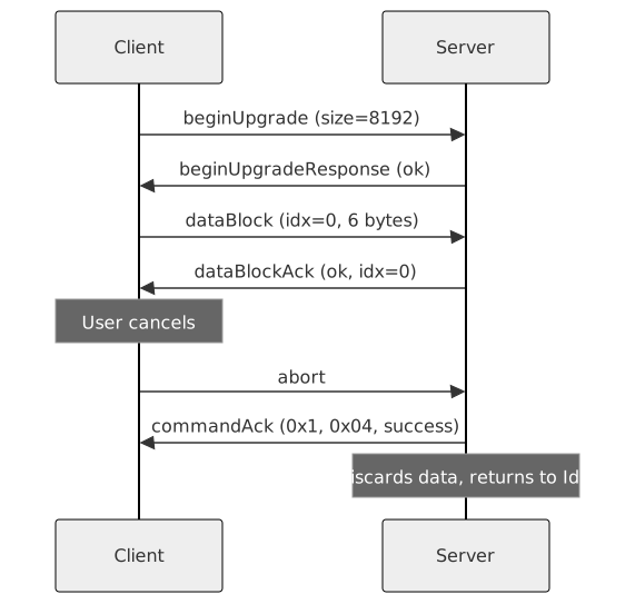
Cancel the current upgrade session and discard received data. Valid in any state except Idle.
Empty payload.
The server transitions to Idle state and responds with a command acknowledgement (System category, success).
4.6 Query Progress (0x05)
Request the current state of the upgrade process.
Empty payload.
The server responds with a Progress Response (0x85).
4.7 Session Timeout
If the server does not receive a DataBlock, Verify, Activate, or
Abort command within a configurable inactivity period (default 30 s)
after a BeginUpgrade or the last DataBlock, the server automatically
aborts the upgrade session and transitions to Idle state. The
application is notified via the OnSessionTimeout() observer
callback.
QueryProgress does not reset the session timer.
The session timeout is configured per-category-instance via
FirmwareUpgradeCategoryServer::Config::sessionTimeout.
5. Message Types — Responses (Server → Client)
Response message type IDs follow the 0x80 + command_id
convention. All responses are sent at
CanPriority::response.
5.1 Begin Upgrade Response (0x80)
| Byte | Field | Type | Description |
|---|---|---|---|
| 0 | Status | uint8 | Error code (see Section 3) |
| 1–2 | PageSize | uint16 | Flash erase page size in bytes |
Total: 3 bytes.
PageSize informs the client of the server’s flash
granularity. This can be used for transfer optimization but is not
required.
5.2 Data Block Ack (0x81)
| Byte | Field | Type | Description |
|---|---|---|---|
| 0 | Status | uint8 | Error code (see Section 3) |
| 1–2 | BlockIndex | uint16 | Index of the acknowledged block |
Total: 3 bytes.
5.3 Verify Response (0x82)
| Byte | Field | Type | Description |
|---|---|---|---|
| 0 | Status | uint8 | 0 = CRC match, 5 = CRC mismatch |
Total: 1 byte.
On success, the server transitions to Complete state.
5.4 Activate Response (0x83)
| Byte | Field | Type | Description |
|---|---|---|---|
| 0 | Status | uint8 | 0 = activating, 6 = not ready |
Total: 1 byte.
5.5 Progress Response (0x85)
| Byte | Field | Type | Description |
|---|---|---|---|
| 0 | State | uint8 | Upgrade state (see Section 2) |
| 1–2 | BlocksReceived | uint16 | Number of blocks received so far |
| 3–4 | TotalBlocks | uint16 | Total blocks expected |
Total: 5 bytes.
6. Typical Flow
6.1 Successful Upgrade
6.2 Aborted Upgrade
6.3 Failed Block Write
7. Implementation Considerations
7.1 Flash Layout
A dual-bank (A/B) layout is recommended:
+-------------------+-------------------+
|  Bank A (Active)  |  Bank B (Staging) |
|  Running firmware |  Incoming image   |
+-------------------+-------------------+
The incoming firmware is written to the inactive bank. On activation, the bootloader swaps the active bank pointer and reboots. If the new firmware fails to start (watchdog timeout), the bootloader reverts to the previous bank.
7.2 Transfer Rate
At 1 Mbit/s with 6 data bytes per CAN frame (~120 bits per frame including framing overhead), the theoretical maximum throughput is approximately 6 KB/s (accounting for ack frames). Faster rates can be achieved by batching multiple data blocks before requiring acks (window-based acknowledgement), which is a possible future extension.
7.3 Security
For production deployments, consider:
- Signature verification: Validate a cryptographic signature (e.g., ECDSA-P256) appended to the firmware image before activation. The signature can be sent in a separate message type or included in the last data blocks.
- Encryption: If firmware confidentiality is required, encrypt the image before transfer and decrypt on the server after verification.
- Rollback prevention: Maintain a monotonic version counter in non-volatile storage; reject firmware with a lower version number.
These security extensions are out of scope for this initial specification but should be implemented for any deployment where the CAN bus is accessible to untrusted parties.
7.4 Large Firmware Images
The uint16 block index limits transfers to ~384 KB. For larger images, two extension strategies are available:
- Set Page (new message type): A “set page” command selects the upper bits of the address, and block indices are offsets within the current page. This allows addressing up to 4 GB with negligible overhead.
- Extended Data Block: A new message type using uint32 block indices, reducing data payload to 4 bytes per frame (256 MB max).
7.5 Error Recovery
- If a block ack indicates
SequenceError, the client should retransmit the expected block. - If a block ack indicates
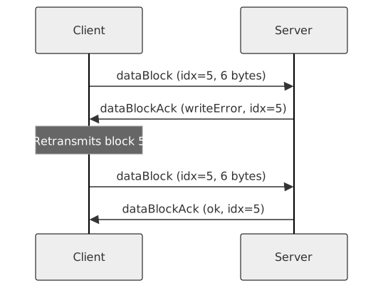
WriteError, the client may retry the same block a limited number of times before aborting. - If the server stops responding, the client should send a Query Progress to determine the current state and resume from the last acknowledged block.
7.6 State Machine
