Motor Alignment — Encoder Zero-Point Calibration
| Field | Value |
|---|---|
| Title | Motor Alignment — Encoder Zero-Point Calibration |
| Type | theory |
| Status | approved |
| Version | 1.0.0 |
| Component | service-alignment |
| Date | 2025-01-01 |
Overview
Motor alignment establishes the correspondence between the incremental encoder position and the electrical rotor angle \(\theta_e\). An incremental encoder measures mechanical shaft rotation from a relative zero point that is arbitrary at power-on. FOC requires the absolute electrical angle to compute the Clarke–Park transform correctly. Without calibration, the angle error \(\Delta\theta\) between the assumed and actual rotor position causes cross-coupling between the d and q axes, degrading torque production and potentially causing instability.
The alignment procedure forces the rotor to a known electrical position by applying a stator field at a fixed electrical angle (typically \(\theta_e = 0\)). The encoder reading at the settled position becomes the alignment offset \(\theta_{offset}\). All subsequent angle calculations subtract this offset:
\[ \theta_e = p \cdot (\theta_m - \theta_{offset}) \]
Prerequisites
| Symbol | Meaning | Unit |
|---|---|---|
| \(p\) | Number of pole pairs | — |
| \(\theta_m\) | Mechanical angle from encoder (raw counts / 2π or rad) | rad |
| \(\theta_e\) | Electrical angle used by FOC | rad |
| \(\theta_{offset}\) | Encoder reading when rotor is at \(\theta_e = 0\) | rad |
| \(\delta\) | Misalignment angle = \(\theta_e - \theta_r\) (field vs rotor) | rad |
| \(K_T\) | Motor torque constant (\(\tau = K_T \cdot i_q\)) | N·m/A |
| \(J\) | Rotor moment of inertia | kg·m² |
| \(B\) | Viscous friction coefficient | N·m·s/rad |
| \(N_{steps}\) | Number of alignment steps per revolution | — |
Mathematical Foundation
1. Physical Principle — Reluctance Torque at Start
A PMSM permanent magnet rotor experiences a torque whenever the stator magnetic field is not aligned with the rotor d-axis. Applying a constant stator current at electrical angle \(\theta_e^{field}\) produces a stator MMF (magnetomotive force) at that electrical angle in the air gap. The interaction with the rotor’s permanent magnet flux creates a synchronising torque:
\[ \tau_{sync} = -K_T \cdot I_d^{field} \cdot \sin(\theta_e^{field} - \theta_r) = -K_{mag} \cdot \sin(\delta) \]
where \(\delta = \theta_e^{field} - \theta_r\) is the angle between the stator field and the rotor d-axis (the north pole of the permanent magnet), and \(K_{mag} > 0\) is a motor-dependent constant.
This is the classical restoring torque of a synchronous machine: \(\tau = -K_{mag}\sin(\delta)\).
Equilibrium: \(\tau_{sync} = 0\) when \(\delta = 0\) or \(\delta = \pi\). The stable equilibrium is \(\delta = 0\), i.e. the rotor d-axis aligns with the applied stator field. The \(\delta = \pi\) equilibrium is unstable.
2. Rotor Settling Dynamics
The rotor motion during alignment is governed by the Newton-Euler equation:
\[ J \ddot{\theta}_r + B \dot{\theta}_r = \tau_{sync} = -K_{mag} \sin(\theta_e^{field} - \theta_r) \]
Linearising around the equilibrium \(\theta_r \rightarrow \theta_e^{field}\) (small \(\delta\), \(\sin\delta \approx \delta\)):
\[ J \ddot{\delta} + B \dot{\delta} + K_{mag}\, \delta = 0 \]
This is a damped second-order system with:
\[ \omega_n = \sqrt{\frac{K_{mag}}{J}}, \qquad \zeta = \frac{B}{2\sqrt{K_{mag} J}} \]
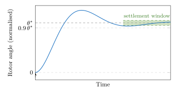
Typical PMSM rotor assemblies are underdamped (\(\zeta < 1\)), so the rotor overshoots and oscillates before settling. The free response is:
\[ \delta(t) = \delta_0 \cdot e^{-\zeta\omega_n t} \left[\cos(\omega_d t) + \frac{\zeta}{\sqrt{1-\zeta^2}}\sin(\omega_d t)\right], \qquad \omega_d = \omega_n\sqrt{1-\zeta^2} \]
See: documentation/theory/images/alignment_settling.svg
(generated by documentation/tools/generate_plots.gp)
3. Single-Step Alignment
The implementation applies a single fixed stator field at \(\theta_e^{field} = 0\). The rotor d-axis is
attracted to this angle and settles there from any starting position
that is not at the unstable equilibrium (\(\delta = \pi\)). In practice, static
friction and motor winding asymmetry prevent the rotor from remaining at
the unstable equilibrium, so the procedure reliably converges for
surface-mounted PMSM and BLDC motors. For interior PMSM motors with
significant magnetic saliency, a rotor that is already near the unstable
equilibrium and is held by static friction may require the
settledThreshold to be tightened and the
testVoltage to be increased to ensure movement.
The field is maintained continuously at a constant duty cycle until the rotor is detected as settled. No stepping or sweeping is performed.
4. Settlement Detection
After applying the field at \(\theta_e = 0\), the controller waits for the rotor to settle. Settlement is detected by a consecutive-sample position-change check:
“The rotor is considered settled when the absolute change in encoder position between successive samples is smaller than \(\epsilon_{threshold}\) for \(M\) consecutive samples.”
Formally, let \(\theta_m[n]\) be the encoder reading at sample \(n\). Settlement is declared when:
\[ \left|\theta_m[n] - \theta_m[n-1]\right| < \epsilon_{threshold} \]
holds for \(M = \texttt{settledCount}\) consecutive samples. If the condition is not met, the counter resets. The threshold \(\epsilon_{threshold}\) must be larger than the encoder quantisation noise but smaller than the expected motion during a half-period of the damped oscillation.
5. Alignment Offset Calculation
Once the motor has settled with the stator field at \(\theta_e^{field} = 0\), the encoder reading \(\theta_m^{settled}\) corresponds to the rotor d-axis being at mechanical angle \(\theta_m^{settled}\). This reading is recorded as the alignment offset:
\[ \theta_{offset} = \theta_m^{settled} \]
During normal FOC operation the corrected electrical angle is:
\[ \theta_e = p \cdot (\theta_m - \theta_{offset}) \pmod{2\pi} \]
This ensures \(\theta_e = 0\) when the rotor is at its original settled position.
6. Torque Production with Angle Error
If the alignment offset is incorrect by \(\Delta\theta\) (in mechanical radians), then the electrical angle error is \(p \cdot \Delta\theta\). The effective torque is reduced:
\[ \tau_{actual} = K_T \cdot i_q \cdot \cos(p \cdot \Delta\theta) \]
For example, a \(10°\) mechanical offset with \(p = 4\) gives a \(40°\) electrical error, reducing torque to \(\cos(40°) \approx 77\%\) of its potential. The d-axis also receives unwanted excitation, potentially demagnetising the permanent magnets under sustained high current.
Block Diagrams
Alignment State Machine

Settling Signal
Numerical Properties
| Property | Value / Condition |
|---|---|
| Field application | Single fixed stator field at \(\theta_e^{field} = 0\) (§3); no stepping |
| Detection threshold | Position change \(< \epsilon_{threshold}\) per check |
| Consecutive checks | \(M\) samples below threshold before declaring settled |
| Offset precision | Limited by encoder resolution (e.g. ±0.5 count) |
| Torque cost | The d-axis field produces the synchronising torque of §2; no \(i_q\) is commanded |
| Worst-case duration | AlignmentConfig::timeout (default 2 s), or
maxSamples samples if that elapses first |
Limitations & Assumptions
- Assumes: The stator field is strong enough to overcome static friction and drag the rotor. For very low currents, the rotor may not follow.
- Assumes: The rotor reaches the stable equilibrium (\(\delta = 0\)), not the unstable one (\(\delta = \pi\)). Large initial misalignment or very low damping can cause incorrect convergence.
- Assumes: Negligible cogging torque relative to \(K_{mag} \cdot I_{align}\). High cogging torque motors may require a higher alignment current.
- Does not handle: Repeated alignment without re-energising (thermal state must be considered).
- Does not handle: Distribution of alignment offset across multiple electrical periods for motors where \(p > 1\) and the mechanical step may span more than one electrical revolution.
References
- Mohan, N. — Advanced Electric Drives: Analysis, Control and Modeling using MATLAB/Simulink, Wiley, 2014.
- Schroedl, M. — “Sensorless control of AC machines at low speed and standstill based on the INFORM method”, Industry Applications Conference, 1996.