Integration Testing Design
| Field | Value |
|---|---|
| Title | Integration Testing Design |
| Type | design |
| Status | accepted |
| Version | 1.1.0 |
| Component | integration-testing |
| Date | 2026-09-21 |
Note — Design-level document: This document describes how the integration tests are structured. It expands on the architecture by specifying component responsibilities, data flows, and design decisions that would not be obvious to a reviewer unfamiliar with the system.
Diagrams: All visuals must be Mermaid fenced code blocks or ASCII art. External image references are not allowed.
Overview
The suite is a black-box driver. It starts a target running the real firmware, speaks to it over the product’s own CAN command set, and asserts on the telemetry and traces that come back. It does not reach into the firmware, does not mock its components, and knows nothing of its internal types.
Scenarios are authored in Gherkin and live in a single directory. A tag decides which target implements a scenario, and the runner is invoked with that tag.
| Tag | Target | Detailed in |
|---|---|---|
@sil |
Real firmware under an emulator, simulated motor | documentation/design/software-in-the-loop.md |
@hil |
Real firmware on hardware, over the bridge | This document |
Earlier revisions described an in-process host fixture that mocked the platform and drove the state machine directly. No such fixture exists, and none is planned: mocking the platform and then asserting on the state machine tests the wiring of the test, not the product.
Responsibilities
Is responsible for: - Starting, stopping and isolating a target for each scenario - Presenting one interactor seam so a scenario reads the same whichever target implements it - Encoding commands and decoding telemetry on the product’s wire format - Describing the simulated world a software-in-the-loop target runs in
Is NOT responsible for: - Control algorithm correctness in the small — that is what the unit tests under each library cover - CAN framing and payload layout — that is the wire contract tests’ job - Substituting for hardware-in-the-loop, which alone exercises silicon, timing and analogue paths
Component Details
The interactor seam
Everything a scenario needs from a target sits behind one interface: lifecycle, command and telemetry transport, and — for a simulated target only — the world the firmware runs in.

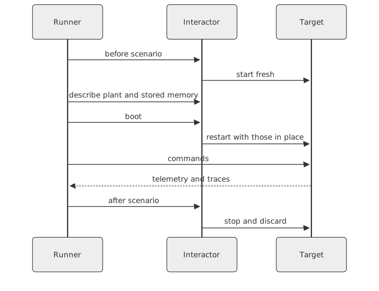
The simulation seam — describe the plant, describe stored memory, restart — defaults to doing nothing and to reporting that simulation is unsupported. A hardware target inherits that default, and a scenario that configures a plant fails loudly rather than quietly testing something else.
Scenario lifecycle
Each scenario gets a fresh target. Setup accumulates in the scenario’s own state and is applied in a single restart, so a scenario that describes a plant, a calibration and a set of algorithms still starts the target once rather than once per description.
Observation
Three channels, all of them the product’s own:
- Telemetry carries the lifecycle state, the fault code, and the measured speed and position.
- Command acknowledgements carry acceptance or the reason for refusal.
- Traces carry what the firmware decided, most importantly which algorithm each loop ended up running, which can differ from what was asked for.
- Plant trajectory, on a simulated target only, carries what the motor actually did, sampled on the control-tick time base, and the tick each command frame was delivered on. This is the channel the performance and disturbance scenarios measure; see the software-in-the-loop design.
Two of the traces are measurements in their own right: the
calibration record the firmware stores
([SM] Calibration record:) and the online estimates it
prints on request ([EST]). Inertia and friction travel in
micro-units on both, because the tracer prints three decimals. The
identification scenarios compare them, and the CAN electrical-parameters
response, against the plant the scenario configured; the terminal
command that asks for the estimates is the product’s own, sent on the
simulated target through the same socket as the CAN frames.
Trace output only drains while the target’s event loop has work, so an assertion that waits for a trace polls telemetry rather than waiting passively. Trace lines are retained across the frames the command path reads, and cleared per scenario and per restart, so an assertion cannot match a line from an earlier boot.
Isolation
Scenarios ran into each other through three shared resources, all now per session: the working directory holding the target’s files, the socket carrying frames, and the captured output.
Interfaces
Provided to step definitions
| Capability | Purpose |
|---|---|
| Lifecycle | Start, stop and restart the target |
| Command transport | Send a category command and await its acknowledgement |
| Telemetry | Await a state, a fault code, or read the measured position |
| Serial capture | Drain and search the target’s trace output |
| Simulation | Describe the plant and the stored calibration and configuration |
| Response | Capture the plant trajectory and measure step and disturbance metrics on it |
Required from the system under test
- A CAN command set covering mode selection, calibration, alignment, enable, disable, setpoints, telemetry requests and fault clearing
- Telemetry reporting state, fault code, measured speed and measured position
- Traces naming the algorithm each control loop is running
- For a simulated target, that it read its plant description at boot
No test-only command is added to the product to make the suite work.
Feature-to-Requirements Mapping
Each scenario carries the requirement identifiers it verifies as tags alongside its runner tag. The traceability matrix is generated from those tags during release, reading the feature directory directly, so the mapping lives with the scenarios rather than in this document where it would rot.