Service: Non-Volatile Memory
| Field | Value |
|---|---|
| Title | Service: Non-Volatile Memory |
| Type | design |
| Status | draft |
| Version | 0.3.0 |
| Component | service-nvm |
| Date | 2026-04-07 |
IMPORTANT — Implementation-blind document: This document describes behavior, structure, and responsibilities WITHOUT referencing code. No code blocks using programming languages (C++, C, Python, CMake, shell, etc.) are allowed. Use Mermaid diagrams to express behavior instead. Prose descriptions of algorithms are encouraged; source-level details are not.
Diagrams: All visuals must be either a Mermaid fenced code block (
```mermaid) or ASCII art inline in the document. External image references using Markdown image syntax are not allowed.
Responsibilities
Is responsible for: - Persisting motor calibration
data (R, L, pole pairs, encoder offset, PID gains, inertia, friction)
and system configuration (current limits, velocity limits, CAN
parameters, telemetry rate, voltage thresholds) across power cycles
using MCU internal EEPROM - Ensuring data integrity on every read
through CRC-32 verification and on every write through read-back
verification - Detecting and signalling version mismatches when a stored
record was written by a different firmware version - Distinguishing the
calibration and configuration regions by per-region magic numbers,
preventing cross-region misinterpretation of data - Providing
non-blocking, callback-based operations — no operation may block the
calling context - Providing a Format operation that erases
both regions to factory state
Is NOT responsible for: - Raw EEPROM hardware access
— all erase, read, and write operations are delegated to injected
NvmRegion instances - Computing the calibration or
configuration values themselves — those are produced by the
identification services and the application - Providing wear-levelling
or journaling — a single record per region is maintained without
historical versioning
Component Details
Logical Regions
The service manages two independent EEPROM regions. Each region holds exactly one record at a time — the latest write replaces any previous record in that address range.
| Region | Magic | Data structure | Data size |
|---|---|---|---|
| Calibration | 0xCAFEF00D |
CalibrationData |
56 bytes |
| Configuration | 0xDEADBEEF |
ConfigData |
20 bytes |
The two regions use different NvmRegion instances
(injected at construction) and can be read, written, and erased
independently. An operation on the calibration region has no effect on
the configuration region and vice versa.
On-Media Record Format
Each region stores a single record consisting of a fixed-size header followed by the data payload. The header fields, in order, are:
| Field | Size | Description |
|---|---|---|
| Magic | 4 bytes | Region identifier (0xCAFEF00D or
0xDEADBEEF) |
| Version | 1 byte | Layout version constant baked into firmware |
| CRC-32 | 4 bytes | CRC-32 of the data bytes only (header excluded) |
| Data | N bytes | Serialised CalibrationData or
ConfigData |
This layout ensures that a calibration record stored in EEPROM cannot be silently misinterpreted as a configuration record (and vice versa) because any cross-region read will fail the magic check immediately.
Integrity Checks on Read
When a region is read back, the following checks are applied in order:
- Magic check — the four-byte magic field must match
the expected value for that region. A mismatch yields
NvmStatus::InvalidData. - Version check — the version byte must match the
version constant compiled into the current firmware. A mismatch yields
NvmStatus::VersionMismatch, allowing the application to handle firmware upgrades gracefully. - CRC-32 check — a CRC-32 is computed over the data
bytes and compared to the stored CRC field. A mismatch yields
NvmStatus::InvalidData.
Only if all three checks pass is the data considered valid and
NvmStatus::Ok reported.
These three checks establish that the record is intact, not
that its values are usable: a record whose CRC matches can
still hold a non-finite float.
FocStateMachineCommon::HasValidCalibration() therefore
applies a plausibility gate on top, requiring the electrical fields to
be finite (and the phase resistance positive) before the restored
calibration can carry the drive to Ready. The same gate
runs on externally supplied calibration in
CmdCompleteExternalCalibration, so a value that arrives
over CAN cannot be persisted either. Positive infinity passes every
> 0 test, which is why finiteness is checked explicitly
rather than inferred from a range comparison.
Write Sequence
Every write operation follows a three-step sequence to protect
against partial writes (e.g., due to unexpected power loss after the
erase but before the write completes). Each step is driven by an
asynchronous callback from the NvmRegion abstraction; no
step blocks:
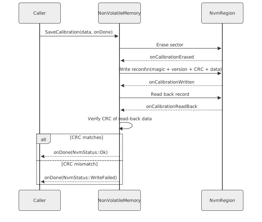
The read-back verification step catches EEPROM hardware faults,
programming errors, and marginal cells that pass the erase but corrupt
the write. NvmStatus::WriteFailed is specifically reserved
for this condition.
EEPROM Address-Space Map
The two NVM regions occupy fixed, non-overlapping address ranges within the MCU EEPROM. Addresses are byte offsets from the start of the EEPROM address space.
| Region | Base address | Size | Content |
|---|---|---|---|
| Calibration | 0 | 128 B | One calibration record |
| Configuration | 128 | 128 B | One configuration record |
| Reserved | 256+ | remainder | Unused; not accessed |
Both regions fit comfortably within the 2048-byte EEPROM available on the TM4C1294 target. ST and Host targets use an in-memory stub of identical layout for regression testing.
Power-Loss Mitigation
EEPROM cells retain data indefinitely once a write word-program cycle completes. The write sequence (erase region → write record → read-back verify) is designed so that power loss at any point leaves the system in a known state:
- Power loss during erase: The region contains
all-0xFF bytes. On next read, the magic check fails and
NvmStatus::InvalidDatais returned — the application must re-run identification or use factory defaults. - Power loss during write: The partially-written
record will fail either the magic check or the CRC-32 check on next
read. The same
InvalidDataresult is returned; no silent corruption is possible. - Power loss during read-back: The write has already
completed. On next power-on, the record will re-read correctly. The
application may retry the write if the previous session reported
WriteFailed.
No journaling or wear-levelling is implemented. Each write operation
overwrites the same address range (erase-then-write), which is
sufficient for infrequent commissioning writes. If frequent writes are
required, a wear-levelling strategy must be added at the
NvmRegion layer.
Buffer Management — No Heap
Each region owns two statically allocated byte arrays:
- Write buffer — sized to hold one complete record
(header + data); populated before the
NvmRegion::Writecall. - Read-back buffer — same size; populated after the
NvmRegion::Readcall for post-write CRC verification.
Both buffers are std::array<uint8_t, recordSize>
members of the service object. They are reused across invocations. No
heap is used at any point.
Concurrency — One Operation At A Time, Device-Wide
Both logical regions are backed by a single EEPROM device, and that device driver serialises access: it accepts exactly one erase, program, or read at a time and treats a second concurrent request as a programming error. Admission control is therefore device-wide, not per region: while any operation is in flight, every entry point — calibration save, load, invalidate, validity check, configuration save, load, reset-to-defaults, and format — is refused. No refused request ever reaches a region.
A refused request never silently disappears. Its callback is invoked
immediately with Busy; the validity check, whose callback
carries a boolean rather than a status, is answered false.
Callers that arm a pending-command callback before issuing a request
therefore always see it complete, and cannot be wedged by a dropped
notification.
Refusal is decided before any internal state is touched, so a caller
that issues a further request from inside a synchronously delivered
Busy callback can only be refused in turn — re-entry cannot
corrupt an in-flight operation. Admission is released just before the
completion callback of the in-flight operation runs, so a follow-up
request issued from that callback is accepted normally.
Callers are expected to treat Busy as “nothing was
written”: any in-memory state speculatively updated in anticipation of a
successful write must be rolled back, and the originating command
rejected cleanly rather than escalated to a fault.
State Machine (Device-Wide)

Error Codes
| Status | Meaning |
|---|---|
Ok |
Operation completed successfully |
InvalidData |
Magic mismatch or CRC-32 mismatch on read |
VersionMismatch |
Version byte in stored record does not match firmware constant |
WriteFailed |
CRC-32 of read-back data does not match what was written |
HardwareFault |
NvmRegion reported a hardware-level error (e.g., erase
or program failure) |
Busy |
Another operation is in flight; nothing was read or written |
Calibration and Configuration Data Fields
CalibrationData (52 bytes total):
| Field | Physical unit | Description |
|---|---|---|
| rPhase | Ω | Measured phase resistance |
| lD | H | Measured d-axis inductance |
| lQ | H | Measured q-axis inductance |
| currentOffsetA/B/C | A | ADC current sensor zero offsets per phase |
| inertia | kg·m² | Estimated rotor inertia |
| frictionCoulomb | N·m | Coulomb (constant) friction |
| frictionViscous | N·m·s/rad | Viscous friction coefficient |
| encoderZeroOffset | rad | Encoder calibration offset (from alignment service) |
| currentLoopBandwidth | rad/s | Current loop closed-loop bandwidth |
| speedLoopBandwidth | rad/s | Speed loop closed-loop bandwidth |
| encoderDirection | — | Polarity correction (+1 or −1) |
| polePairs | — | Number of motor pole pairs |
ConfigData (20 bytes total):
| Field | Physical unit | Description |
|---|---|---|
| canNodeId | — | CAN bus node identifier |
| canBaudrate | bit/s | CAN bus baud rate |
| telemetryRateHz | Hz | Rate at which telemetry frames are sent |
| encoderResolution | — | Encoder counts per mechanical revolution |
| defaultControlMode | — | Control mode selected on power-up |
| currentAlgorithm | — | Current-loop algorithm selected on power-up |
| speedAlgorithm | — | Speed-loop algorithm selected on power-up |
| positionAlgorithm | — | Position-loop algorithm selected on power-up |
The four selection fields are stored as raw byte identifiers. A record can pass the integrity check and still hold a byte outside the valid range for its selection, so each value is range-checked against its algorithm set before it is applied on power-up. A value outside the range, or a selection the current motor parameters do not support, leaves the loop on its built-in default and the stored byte is corrected to match what is actually running.
Interfaces
Provided
| Interface | Purpose | Contract |
|---|---|---|
SaveCalibration(data, onDone) |
Erases calibration sector, writes record, verifies read-back | onDone(NvmStatus) fires exactly once; Busy
if the device is occupied |
LoadCalibration(onDone) |
Reads and integrity-checks the calibration record | onDone(NvmStatus) fires exactly once; Busy
if the device is occupied |
InvalidateCalibration(onDone) |
Erases the calibration sector without writing a new record | Makes IsCalibrationValid return false;
onDone(NvmStatus) fires once |
IsCalibrationValid(onDone) |
Reads and integrity-checks the calibration record, reporting validity only | onDone(bool) fires exactly once; false if
the device is occupied |
SaveConfig(data, onDone) |
Same write+verify sequence for the configuration region | onDone(NvmStatus) fires exactly once; Busy
if the device is occupied |
LoadConfig(onDone) |
Reads and integrity-checks the configuration record | onDone(NvmStatus) fires exactly once; Busy
if the device is occupied |
ResetConfigToDefaults(onDone) |
Writes a record containing factory-default values to the configuration region | Follows the same erase/write/verify sequence as
SaveConfig |
Format(onDone) |
Erases both calibration and configuration regions | onDone(NvmStatus) fires once, after both regions are
erased |
Required
| Interface | Purpose | Contract |
|---|---|---|
NvmRegion (calibration instance) |
Abstracts raw EEPROM write and read for the calibration address range | Must be backed by a dedicated EEPROM address range; must not be shared with any other user |
NvmRegion (configuration instance) |
Abstracts raw EEPROM write and read for the configuration address range | Must be backed by a dedicated EEPROM address range separate from the calibration range |