FOC Speed Control
| Field | Value |
|---|---|
| Title | FOC Speed Control |
| Type | design |
| Status | draft |
| Version | 0.1.0 |
| Component | foc-speed |
| Date | 2026-04-07 |
IMPORTANT — Implementation-blind document: This document describes behavior, structure, and responsibilities WITHOUT referencing code. No code blocks using programming languages (C++, C, Python, CMake, shell, etc.) are allowed. Use Mermaid diagrams to express behavior instead. Prose descriptions of algorithms are encouraged; source-level details are not.
Diagrams: All visuals must be either a Mermaid fenced code block (
```mermaid) or ASCII art inline in the document. External image references using Markdown image syntax are not allowed.
Responsibilities
Is responsible for: - Executing the two-level FOC
cascade: an outer speed PID loop (1 kHz by default) and an inner current
control loop (20 kHz) - Estimating rotor angular velocity from
successive mechanical angle samples using finite differences with
wrap-around compensation - Regulating rotor speed to the commanded
setpoint in radians per second - Producing the Iq (quadrature current)
setpoint that drives the inner torque loop, bounded by a configurable
current limit - Registering an outer-loop callback with the
LowPriorityInterrupt interface so that the outer loop fires
at the correct prescale ratio - Providing
OuterLoopFrequency() so that the application can schedule
the LowPriorityInterrupt at the correct rate - Arming and
resetting all three PID controllers (speed, d-axis, q-axis) on Enable /
Disable
Is NOT responsible for: - Reading phase currents or encoder position directly from hardware — these are supplied by the Runner - Writing duty cycles to PWM hardware — duty cycles are returned to the Runner - Position control or any loop beyond the speed layer - Flux weakening (Id is always commanded to 0 A)
Component Details
Two-Loop Cascade Architecture
Speed control builds on the torque control loop by adding a supervisory outer loop. The two loops operate at different rates and in different interrupt contexts:
| Loop | Rate | Context | Input | Output |
|---|---|---|---|---|
| Inner loop | 20 kHz | High-priority FOC ISR | Phase currents, θm | PWM duty cycles |
| Outer loop | 1 kHz | Low-priority interrupt | θm from last inner cycle | Iq setpoint (Ampere) |
The inner loop is identical to the torque control loop described in the FOC Torque Control design document. The outer loop adds the speed PID and the speed estimation step.

Outer Loop — Speed Estimation and Speed PID
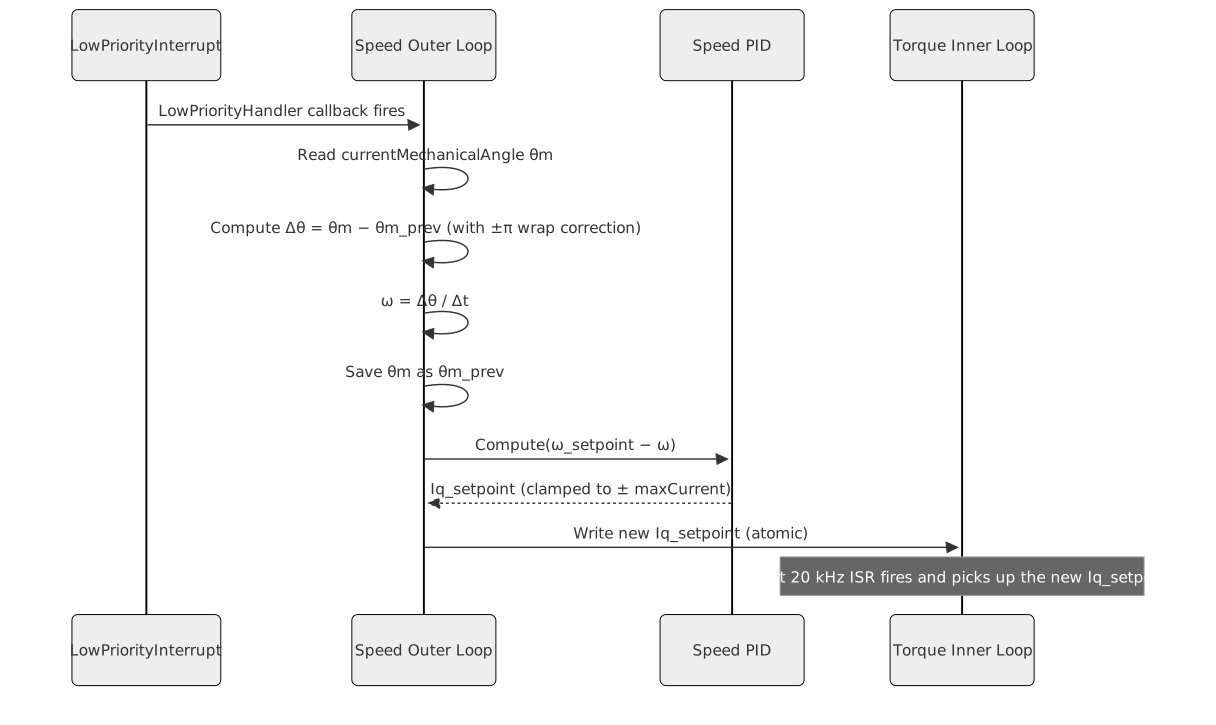
The outer loop is triggered by the LowPriorityInterrupt
at a prescale ratio determined by the ratio of the inner-loop frequency
to the desired outer-loop frequency (e.g., 20 kHz / 1 kHz = 20 inner
cycles per outer cycle).
Speed estimation by finite difference:
The angular velocity is estimated from the difference between the current mechanical angle sample and the previous angle sample, divided by the outer-loop period Δt:
ω = Δθ / ΔtBecause the encoder angle wraps around at 2π, the raw angle difference may be discontinuous at the wrap boundary. Wrap-around compensation applies a correction: if the computed Δθ is greater than +π, it is shifted by −2π; if it is less than −π, it is shifted by +2π. This produces a signed angular velocity in the range (−π/Δt, +π/Δt) radians per second for any physical speed below half the Nyquist rate of the sampling interval.
Speed PID:
The speed PID receives the speed error (setpoint minus estimate) and produces the Iq setpoint. Its output is clamped to ± maxCurrent (in Ampere), which directly limits the peak torque the motor can apply while tracking the speed command. This clamp is the primary over-current protection for the speed-control mode.
The d-axis setpoint is 0 A, except while an online electrical
estimator is attached: the cascade then adds a ±2.5 % of maxCurrent, 10
Hz square wave so the winding resistance stays observable (see
service-electrical-ident.md, Excitation).
LowPriorityInterrupt — Outer Loop Scheduling
The LowPriorityInterrupt is an abstract scheduling
interface. The speed control component registers its outer-loop handler
with this interface at construction time. The inner-loop ISR counts
cycles and triggers the LowPriorityInterrupt at the
appropriate prescale ratio, causing the outer-loop handler to execute
without RTOS involvement.
The registered handler captures the cascade instance, so its lifetime
is bound to that instance. The cascade calls Unregister()
from its destructor; after Unregister() returns, an already
queued trigger must be discarded rather than dispatched, so a mode
switch that destroys the cascade cannot leave a handler pointing at
freed storage.
OuterLoopFrequency() returns the configured outer-loop
rate so the application layer can assert or configure the LPI trigger
frequency correctly.
Enable and Disable
Enable: resets and arms all three PID controllers (speed, d-axis, q-axis). The last speed setpoint is preserved so the motor resumes commanding toward the previous target.
Disable: disarms all three PIDs.
Calculate() returns zero duty cycles. The outer loop
continues to receive its LPI callbacks but produces no Iq output while
disarmed.

Interfaces
Provided
| Interface | Purpose | Contract |
|---|---|---|
| Configure | Supplies the motor model, including the pole-pair count used for the electrical angle. | Must be called before the first Calculate(). Must not
be changed while Enabled. |
| Enable | Arms all three PIDs and resets their integrator state. | Safe to call repeatedly. Speed setpoint is preserved. |
| Disable | Disarms all PIDs and forces zero duty cycle output. | Safe to call from any context. |
| SetCurrentTunings | Sets the current loop closed-loop bandwidth. | Gains are derived from the motor model and normalised internally.
Takes effect on the next Calculate(). |
| SetSpeedTunings | Sets the speed loop closed-loop bandwidth. | Gains are derived from the mechanical model supplied through
ConfigureMechanics(). Output is clamped to ±
maxCurrent. |
| SetPoint | Sets the speed setpoint in radians per second. | Written atomically; used on the next outer-loop cycle. |
| Calculate | Executes the inner 20 kHz FOC torque loop for one cycle. | Called from the FOC ISR; returns PhasePwmDutyCycles.
Must not block. |
| OuterLoopFrequency | Returns the configured outer-loop frequency in Hz. | Pure query; no side effects. Can be called before Enable. |
| SetOnlineMechanicalEstimator | Attaches an online mechanical parameter estimator (optional). | If attached, the estimator is updated automatically on each outer-loop cycle. No separate estimator Enable/Disable interface is defined here; detach or omit the estimator to stop updates. |
| SetOnlineElectricalEstimator | Attaches an online electrical parameter estimator (optional). | If attached, the estimator is updated each outer-loop cycle from window averages the inner loop accumulates, and a d-axis square wave is added to the current reference so the resistance is observable. Assumes non-salient motor (Ld ≈ Lq). |
| ObserveMotion | Reports the window speed, window-mean q-axis current and speed reference. | Written by the control interrupts, read from the event loop; feeds telemetry (REQ-INT-014) and the encoder plausibility monitor (REQ-SM-028). |
Required
| Interface | Purpose | Contract |
|---|---|---|
| LowPriorityInterrupt | Provides the callback registration point for the outer-loop speed PID handler. | The inner-loop ISR triggers the LPI at the correct prescale ratio. The outer-loop handler must execute within its own interrupt context, not the 20 kHz ISR context. |
Data Model
| Entity | Field | Type / Unit | Range | Notes |
|---|---|---|---|---|
| Speed setpoint | ω_sp | RadiansPerSecond (float) | ± mechanical max | Written by application; applied on next outer-loop tick |
| Estimated speed | ω | RadiansPerSecond (float) | computed from Δθ/Δt | Computed each outer-loop cycle |
| Speed PID output | Iq_sp | Ampere (float) | ± maxCurrent | Written to inner loop; clamped by speed PID output limit |
| d-axis setpoint | Id_sp | Ampere (float) | 0 A; ±2.5 % Imax at 10 Hz with estimator | SPMSM maximum torque per ampere |
| Previous angle | θm_prev | Radians (float) | [0, 2π) | Saved each outer cycle for finite-difference estimator |
| Outer loop period | Δt | Seconds (float) | 1 / outer_frequency | Constant after construction |
| Pole pairs | P | Integer (unsigned) | ≥ 1 | Motor property |
| Max current | maxCurrent | Ampere (float) | > 0 | Upper bound on Iq setpoint from speed PID |
Sequence Diagrams
Single Outer-Loop Cycle (1 kHz LPI Event)
Online Estimator Update Within Outer-Loop Cycle
When online estimators are attached and enabled, each 1 kHz outer-loop cycle also feeds observations to them after the speed PID step:
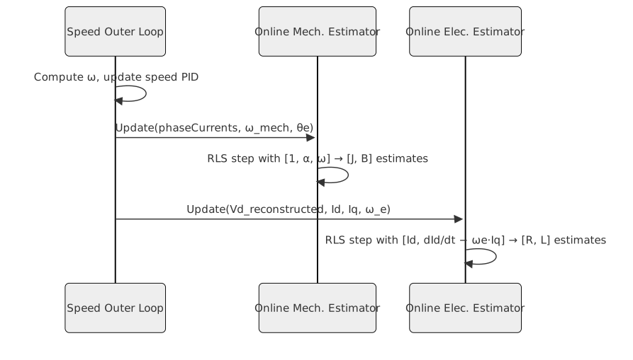
Vd_reconstructed is the d-axis voltage back-computed
from the last normalized Vd output of the inner loop and the DC bus
voltage.
Constraints & Limitations
| Constraint | Value / Description |
|---|---|
| Inner loop rate | 20 kHz — called from the FOC ISR once per PWM period. |
| Outer loop rate | Configurable; default 1 kHz. Must be a integer divisor of 20 kHz. |
| Iq saturation | Speed PID output clamped to ± maxCurrent (Ampere). This limits peak torque. |
| Speed estimator wrap threshold | Assumes physical speed below π / Δt rad/s (half the Nyquist limit of the outer-loop sampling rate). |
| No flux weakening | Id = 0 is fixed. Operating above base speed without flux weakening is the application’s responsibility. |
| LPI scheduling | The outer loop does not use an RTOS. The inner loop ISR triggers the LPI — no timer or task involved. |
| Cycle budget | Inner loop Calculate() must complete in <= 4500
cycles (75% of the 6000-cycle control period at 120 MHz / 20 kHz). |
| Setpoint atomicity | The Iq setpoint written by the outer loop must be read atomically by the inner loop on 32-bit ARM targets. |
Controller Alternatives
The speed PID described above is one of several selectable strategies
for the outer speed loop. Alternative controllers — LQI, ADRC, and
Two-DOF — are described in
documentation/theory/advanced-controllers.md
(speed-loop-lqi.md, speed-loop-adrc.md,
speed-loop-two-dof.md). Plant model foundations are in
documentation/theory/foc-plant-models.md.
The runtime selection mechanism is described in
documentation/design/controller-selection.md.