Runtime Controller Selection
| Field | Value |
|---|---|
| Title | Runtime Controller Selection |
| Type | design |
| Status | accepted |
| Version | 0.3.0 |
| Component | controller-selection |
| Date | 2026-08-17 |
IMPORTANT — Implementation-blind document: This document describes behavior, structure, and responsibilities WITHOUT referencing code. No code blocks using programming languages (C++, C, Python, CMake, shell, etc.) are allowed. Use Mermaid diagrams to express behavior instead. Prose descriptions of algorithms are encouraged; source-level details are not.
Diagrams: All visuals must be either a Mermaid fenced code block (
```mermaid) or ASCII art inline in the document. External image references using Markdown image syntax are not allowed.
Responsibilities
Is responsible for: - Maintaining a collection of
concrete controller instances for each of the three FOC loops (current,
speed, position), all stored in fixed-size, statically-allocated storage
without heap use - Activating one controller per loop at runtime by
constructing it in place from the available set - Routing each loop’s
per-sample computation to the active controller with zero
virtual-dispatch overhead through type-aware dispatch (variant visit) -
Enforcing that algorithm selection is only permitted while the active
mode is stopped (Idle or Ready) and has no NVM
work outstanding — not only while the motor is disabled - Propagating
motor model parameters from the online RLS estimators to the newly
selected controller immediately after selection - Persisting the active
algorithm identifier for each loop to non-volatile memory upon each
selection - Restoring the persisted algorithm identifiers at boot and
re-configuring the controllers from NVM before the first Enable command
- Exposing algorithm selection to the CLI terminal
Is NOT responsible for: - Implementing the control algorithms themselves — each concrete controller is self-contained - Executing FOC transforms (Clarke, Park, SVM) — these remain inline in the FOC loop - Estimating motor model parameters — that is the responsibility of the RLS identification services - Safety monitoring or fault detection — the FOC state machine owns these - Tuning algorithm-specific parameters beyond what is derivable from motor model parameters
Component Details
Part A — Algorithm Enumeration
Each of the three FOC loops has an independent enumeration of available algorithm choices.
Each loop has its own independent algorithm enumeration. An algorithm is only valid for the loop it is listed under; there is no sharing of algorithm identifiers across loops.
Current loop — executes at 20 kHz in the FOC ISR:
| Algorithm | Description |
|---|---|
| PID | Incremental PI baseline |
| Decoupled PID | PI plus cross-coupling and back-EMF feedforward |
| Deadbeat | One-step or two-step predictive voltage inversion |
| Sliding-mode | Robust switching control with boundary-layer saturation |
Speed loop — executes at 1 kHz in the low-priority handler:
| Algorithm | Description |
|---|---|
| PID | Incremental PI baseline |
| LQI | DARE-computed state-feedback with integral augmentation |
| ADRC | Extended-state observer + active disturbance cancellation |
| Two-DOF | Reference pre-filter + PI; decoupled tracking and stiffness tuning |
Position loop — executes at 1 kHz in the low-priority handler:
| Algorithm | Output | Description |
|---|---|---|
| PID | Speed reference | Incremental PI on the wrapped position error |
| Cascade P | Speed reference | Industry-standard P position → speed loop; single gain |
| LQR | Current reference | DARE-computed state feedback on (θ, ω) |
| LQI | Current reference | LQR with position integral augmentation |
| Two-DOF | Speed reference | Reference pre-filter + PI; tracking and stiffness tune apart |
Each position algorithm declares whether it produces a speed reference or a current reference. A speed reference runs through the existing speed and current loops unchanged. A current reference bypasses the speed loop and feeds the current loop directly, because the state feedback laws already regulate speed as part of their own state vector; running them on top of a speed loop would stack two regulators on the same state.
The enumeration for each loop is fixed at build time. The default for all loops at first boot is PID.
Part B — Heap-Free Variant Storage
All concrete controller instances for a given loop are held simultaneously in a single fixed-size discriminated union (a type-safe union that tracks which alternative is currently active). Only the active alternative is live at any time; inactive alternatives exist as constructed but dormant objects.
Switching the active algorithm constructs the new controller in place inside the union, destroying the previous one, with no dynamic memory allocation. The total storage required is the size of the largest concrete controller in the set, determined at build time.
This pattern is identical to the one already used by
ControlModeStateMachine for switching between Torque,
Speed, and Position control modes.

Part C — Hot-Path Dispatch via Type-Aware Visit
The per-sample Compute call — which runs at 20 kHz in
the current loop ISR — must not incur indirect dispatch through a
virtual base-class pointer, as this prevents the compiler from inlining
and optimising the critical arithmetic.
Dispatch is performed by visiting the discriminated union: the visitor examines the stored type tag and jumps directly to the concrete implementation, allowing the compiler to devirtualize the call and inline the arithmetic. The resulting machine code is equivalent to a switch table with a direct function body inlined at each case, not a vtable indirection. There is no allocation and no heap touch in this path.
The visit call is the only place where Compute is
invoked in the ISR; all controller-specific setup, gain computation, and
model updates occur off the hot path in the configuration routine.

Part D — State Gating
Algorithm selection is a configuration-time operation, not a run-time
one. It is only permitted while the active mode’s lifecycle state
machine is stopped (Idle or
Ready) and has no asynchronous work outstanding, including
any write to the shared non-volatile memory. A request arriving while
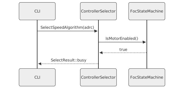
the motor is Enabled, Calibrating or in
Fault, or while such a write is outstanding, is rejected
immediately with Busy without altering the active algorithm
or any controller state.
The guard is the same one
ControlModeStateMachine::Select applies to mode changes
(documentation/design/state-machine.md C2b). The cascades’
own refusal while enabled remains underneath it.

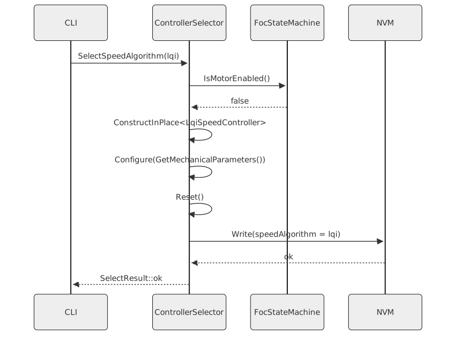
On a successful selection, the sequence is: 1. Construct the new controller in place in the union (destroying the previous one). 2. Update the active algorithm identifier. 3. Configure the new controller with the current motor model parameter snapshot from RLS. 4. Reset the new controller’s internal integrators and observer state to zero. 5. Persist the algorithm identifier to NVM.
Step 4 (Reset) ensures the controller starts from a clean state regardless of what state the motor or the previous controller was in.
Part D2 — Design Feasibility for the Position State Feedback Laws
The position plant is a near double integrator, which makes its discrete Riccati solve far more fragile than the first-order speed plant. Solved on the raw state \((\theta, \omega)\) at a 1 kHz outer rate it does not converge at all in single precision. Three conditioning measures make it tractable:
- Time-scaled state. The design runs on \((\theta,\ \omega T_s)\) rather than \((\theta,\ \omega)\), so the state matrix becomes \(A = \begin{bmatrix} 1 & 1 \\ 0 & 1 - \tfrac{B_f}{J} T_s \end{bmatrix}\) with every entry near unity.
- Normalised input. The input matrix is fixed at \(B = [0\ \ 1]^T\) by folding the actuator authority \(\tfrac{K_t}{J} T_s^2 I_{max}\) into a scalar applied to the resulting command. The Riccati recursion therefore never sees the motor’s torque scale.
- Bandwidth-derived effort weight. \(R = 1 / (\omega_{bw} T_s)^2\), with \(\omega_{bw} T_s\) clamped to \([10^{-3},\ 0.5]\). This makes settling time
scale as \(2 / \omega_{bw}\) seconds
with roughly 4 % overshoot across four decades of bandwidth, so
bandwidthremains the single aggressiveness knob it is for every other loop.
The state weights are shape knobs only.
positionErrorWeight anchors the cost at one and the
remaining weights enter as ratios against it, clamped to \([10^{-3},\ 10^3]\). Anchoring matters for
more than conditioning: if the position entry of \(Q\) can reach zero the cost stops
penalising the integrator state and the recursion has no stabilising
solution to find.
These measures shrink but do not eliminate non-convergence.
Lqr::TryCreate is therefore used throughout in preference
to the aborting constructor, and feasibility is part of the selection
rule rather than an afterthought:
PositionControllerTraits::IsSelectableruns the actual Riccati solve for LQR and LQI. A selection whose design does not converge returnsinvalidParametersand leaves the previously active algorithm running, so the motor never ends up holding a silently dead loop.SetPositionTuningsis refused outright while the motor is enabled, returningbusy. A live motor is not a safe place to redesign the law that is holding it.- When disabled,
SetPositionTuningsrevalidates the new tunings against the active algorithm and rejects them if the design fails, keeping the last accepted gains live.
This is why SetPositionTunings returns
SelectResult where the current and speed loops return
void: those loops derive their gains algebraically and
cannot fail.
IntegralStateFeedbackLqi is not used for the LQI
position law even though it now offers a TryCreate factory.
It augments the plant with C · (−Ts), which reintroduces
the sample period into the integral row and undoes the time scaling
above; at a 1 kHz outer rate that row is three orders of magnitude
smaller than the rest of the matrix and the solve stops converging. The
augmentation is therefore written out explicitly in the scaled
coordinates, where the integral state simply accumulates the position
deviation per sample, and solved with
Lqr<float, 3, 1>::TryCreate.
Part E — Motor Model Parameter Flow
When an algorithm is selected, it is immediately configured using the most recent snapshot of the motor model parameters. The parameters are drawn from two sources:
- Electrical parameters (
Rs,Ls,ψf,Vdc, pole pairs): from the electrical RLS identification service, as set by the calibration sequence. - Mechanical parameters (
J,Bf,Kt): from the mechanical RLS identification service, available after the speed/position calibration phase.
The configuration call is a one-time operation that computes all gains and pre-computed matrices (e.g., DARE solution for LQR/LQI) before the controller becomes active. The ISR then executes only the pre-computed gain application.
If the RLS estimators produce updated parameter estimates during
operation (continuous identification mode), the active controllers are
not automatically reconfigured. Reconfiguration with updated parameters
requires a new SelectAlgorithm call (or an explicit
ReconfigureFromCurrentParameters command), which requires
the motor to be disabled.

Part F — CLI Interface
ControlModeStateMachine registers the selection commands
on the terminal.
| Command | Alias | Effect |
|---|---|---|
select_current_algorithm <alg> |
sca |
Selects the current-loop algorithm |
select_speed_algorithm <alg> |
ssa |
Selects the speed-loop algorithm |
select_position_algorithm <alg> |
spa |
Selects the position-loop algorithm |
active_algorithms |
aa |
Prints the active algorithm for each loop |
Valid <alg> tokens are the lower-case algorithm
names: pid, decoupled, deadbeat
and sliding for the current loop; pid,
lqi, adrc and twodof for the
speed loop; and pid, cascadep,
lqr, lqi and twodof for the
position loop. Unknown tokens produce a usage error without altering
state.
The commands enforce the motor-enabled guard described in Part D and
report the SelectResult verbatim, so an operator always
learns why a selection was refused.
Part G — CAN Interface
Algorithm selection is not exposed over CAN. The
can-lite foc_motor category defines no frame
for it, and the CAN bridge does not reinterpret an existing frame to
carry an algorithm identifier. Selection and query are CLI-only; see
REQ-CTRL-001 and REQ-CTRL-013.
Part H — Required Parameters Per Controller
Each controller algorithm has specific parameter dependencies. These dependencies determine what must be available before that algorithm can be selected, and who is responsible for providing each value.
Parameter Sources
Parameters come from three distinct sources with different availability windows:
| Source | Parameters | Available after |
|---|---|---|
| Motor datasheet (static) | Pole pairs \(p\), flux linkage \(\psi_f\), peak current \(I_{q,max}\) | Before any run |
| Electrical RLS calibration | \(R_s\), \(L_s\), \(V_{dc}\) | After electrical identification |
| Mechanical RLS calibration | \(J\), \(B_f\), \(K_t = \tfrac{3}{2} p \psi_f\) | After mechanical identification |
\(\psi_f\) is the only datasheet value not directly observable by the RLS estimators. If unavailable from the datasheet, it can be derived from the rated torque constant: \(\psi_f = K_{t,rated} \cdot 2/(3p)\).
\(V_{dc}\) is measured dynamically during operation; a nominal value must be known at configuration time for gain normalisation.
Per-Algorithm Parameter Requirements
Current loop:
| Parameter | PID | Decoupled PID | Deadbeat | Sliding-mode |
|---|---|---|---|---|
| \(R_s\), \(L_s\) (electrical RLS) | Required | Required | Required (tight) | Required |
| \(\psi_f\) (datasheet) | Not required | Required — back-EMF FF | Not required | Required — back-EMF FF |
| \(V_{dc}\) | Required — normalisation | Required — normalisation | Required — normalisation | Required — normalisation |
| \(I_{q,max}\) | For output clamp | For output clamp | For clamp | For switching gain sizing |
Deadbeat requires the tightest RLS convergence.
Sliding-mode applies the same decoupling feedforward as Decoupled PID, and for the same reason: its sliding surface is designed on the decoupled per-axis RL plant, so the cross-coupling and the back-EMF are disturbance to it. Sizing the switching gain to reject them outright is not viable — at 1000 rad/s electrical on a 0.01 Wb rotor the back-EMF alone is several times the authority the default gain commands, and raising the gain that far would put the boundary-layer ratio outside the range in which the error map contracts. Feeding them forward leaves the switching term the residue it is sized for.
Speed loop:
| Parameter | PID | LQI | ADRC | Two-DOF |
|---|---|---|---|---|
| \(J\), \(B_f\) (mechanical RLS) | Not required | Required — DARE plant | Required — \(b_0=K_t/J\) | Not required |
| \(K_t\) (derived) | Not required | Required | Required | Not required |
| \(I_{q,max}\) | For clamp | Required — R weight | For clamp | For clamp |
ADRC is the most forgiving: \(b_0\) tolerates ±50% error. Two-DOF and PID require no mechanical RLS and are available as soon as electrical calibration completes.
Position loop:
| Parameter | PID | Cascade P | LQR | LQI | Two-DOF |
|---|---|---|---|---|---|
| \(J\), \(B_f\) (mechanical RLS) | Not required | Not required | Required | Required | Not required |
| \(K_t\) (derived) | Not required | Not required | Required | Required | Not required |
| \(I_{q,max}\) | For clamp | Speed-loop dep. | Required — R weight | Required — R weight | For clamp |
Tuning Knobs (design choices, not estimated)
Each loop exposes one tuning record shared by all of its algorithms: a single closed-loop bandwidth plus a small set of law-specific weights. The record is not estimated — it encodes the operator’s performance intent, and each algorithm reads only the fields that apply to it. Gains are always derived from the bandwidth and the motor model, never supplied per axis.
Current loop:
| Knob | Default | Consumed by |
|---|---|---|
| Bandwidth | 2π·1000 rad/s | PID, Decoupled PID |
| Switching gain | 0.2 | Sliding-mode |
| Boundary layer | 0.5 | Sliding-mode |
| Two-step variant | off | Deadbeat |
The sliding-mode error map inside the boundary layer contracts only while the switching gain stays below the boundary layer, so the ratio of the two is bounded by design. This is why the back-EMF is handled by feedforward rather than by a larger switching gain.
Speed loop:
| Knob | Default | Consumed by |
|---|---|---|
| Bandwidth | 2π·30 rad/s | PID, ADRC |
| Speed error weight | 1.0 | LQI |
| Integral weight | 0.1 | LQI |
| Observer bandwidth ratio | 5.0 | ADRC |
| Reference time constant | 5.3 ms | Two-DOF |
Position loop:
| Knob | Default | Consumed by |
|---|---|---|
| Bandwidth | 2π·3 rad/s | PID, Cascade P, LQR, LQI |
| Position error weight | 1.0 | PID, LQR, LQI |
| Speed error weight | 0.1 | LQR, LQI |
| Integral weight | 0.05 | PID, LQI |
| Reference time constant | 53 ms | Two-DOF |
Two-DOF on both outer loops derives its feedback part from the same bandwidth as the corresponding PID law and adds only the reference pre-filter time constant on top.
Of these knobs only the current loop bandwidth and the speed loop bandwidth are persisted, as part of the calibration record. The remaining weights and the position loop bandwidth are not stored and return to their defaults on boot.
Readiness Gate per Algorithm
The selection guard (Part D) enforces not only the
stopped-and-not-busy check but also a parameter-readiness check.
Attempting to select an algorithm whose required parameters are not yet
available returns InvalidParameters rather than
ok.

The readiness state for each parameter source is:
| Source | Readiness condition |
|---|---|
| Datasheet params (\(p\), \(\psi_f\)) | Set during motor configuration before calibration |
| Electrical RLS | Calibration sequence reached and completed the electrical identification step |
| Mechanical RLS | Calibration sequence reached and completed the mechanical identification step |
Current-loop algorithms (Decoupled PID, SMC) become selectable after electrical identification. Speed and position algorithms (LQI, ADRC, LQR) additionally require mechanical identification.
Part I — NVM Persistence
The active algorithm identifier for each loop is stored as three
additional fields in the existing ConfigData structure
alongside defaultControlMode. On boot:
- NVM is read and validated.
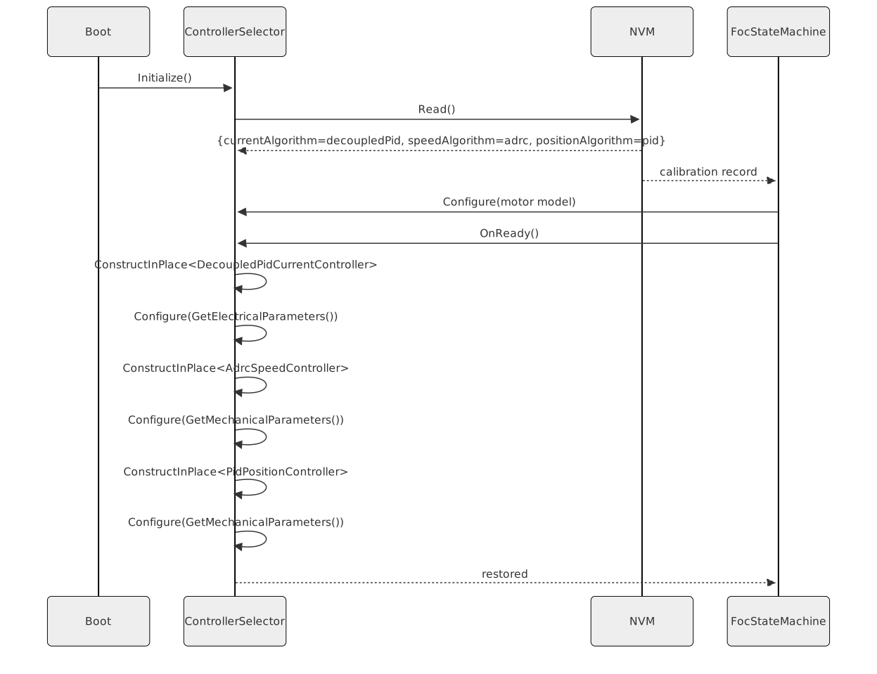
- If valid, the persisted algorithm identifiers are loaded and used to configure each loop’s controller using the also-persisted motor model parameters.
- If invalid (first boot, CRC mismatch), the default (PID for all loops) is used and written.
Restoration is driven by the state machine’s transition into
Ready, not by construction of the control mode: the motor
model only reaches the loops when the calibration record has been
applied, which happens asynchronously after the NVM read completes.
Applying the persisted identifiers any earlier would reject every
model-dependent algorithm (deadbeat, decoupled PID, speed LQI, speed
ADRC, position LQR, position LQI).
Two failure kinds are distinguished when a persisted identifier cannot be activated:
| Failure | Effect on ConfigData |
|---|---|
| Byte out of enum range, or names no algorithm for that loop | Corrected to the active algorithm — the record is meaningless |
Valid algorithm, not selectable yet
(InvalidParameters) |
Preserved, and retried on the next entry to Ready |
The non-volatile memory serves one write at a time and answers a
concurrent one with busy. A selection’s write that comes back
busy is retried after a short delay until it lands; while it or any
other write to that memory is outstanding, selections, mode changes and
calibration are refused with busy
(documentation/design/state-machine.md C2a).
The persistence ensures that an operator who selects ADRC for the
speed loop does not need to repeat the selection after every power
cycle. The motor state machine will transition directly to
Ready with the previously selected algorithms active, ready
to enable.
Interfaces
Provided
| Interface | Purpose | Contract |
|---|---|---|
| SelectCurrentAlgorithm | Selects the active current-loop controller by enum value | busy unless stopped with no pending work (Part D).
Effect is immediate if ok. |
| SelectSpeedAlgorithm | Selects the active speed-loop controller by enum value | As above. |
| SelectPositionAlgorithm | Selects the active position-loop controller by enum value | As above. |
| ActiveCurrentAlgorithm | Returns the currently active current-loop algorithm identifier | Always returns a valid enum value. Never blocks. |
| ActiveSpeedAlgorithm | Returns the currently active speed-loop algorithm identifier | As above. |
| ActivePositionAlgorithm | Returns the currently active position-loop algorithm identifier | As above. |
| ComputeCurrentControl | Dispatches to the active current controller for one sample | Called at 20 kHz from ISR. Zero heap. No virtual dispatch. |
| ComputeSpeedControl | Dispatches to the active speed controller for one sample | Called at 1 kHz from low-priority handler. |
| ComputePositionControl | Dispatches to the active position controller for one sample | Called at 1 kHz from low-priority handler. |
| ReconfigureFromCurrentParameters | Re-applies the latest RLS snapshot to the active controllers without changing algorithm | Motor must be disabled. |
Required
| Interface | Purpose | Contract |
|---|---|---|
| IsMotorEnabled | Checks whether the motor state machine is in the Enabled state | Used to enforce the selection guard. Must be callable from off the ISR. |
| GetElectricalParameters | Retrieves the current RLS estimate of Rs,
Ls, ψf, Vdc, pole pairs |
Called during Select and ReconfigureFromCurrentParameters. |
| GetMechanicalParameters | Retrieves the current RLS estimate of J,
Bf, Kt |
Called during Select and ReconfigureFromCurrentParameters for speed/position loops. |
| NvmWrite | Persists the algorithm identifiers to non-volatile storage | Called once per successful selection. Must not block the hot path. |
| NvmRead | Reads persisted algorithm identifiers at boot | Called during boot initialization before any Enable. |
Data Model
| Entity | Field | Type / Unit | Range | Notes |
|---|---|---|---|---|
| CurrentAlgorithm | enum | uint8 | pid, decoupledPid, deadbeat, slidingMode | Selectable current-loop strategy |
| SpeedAlgorithm | enum | uint8 | pid, lqi, adrc, twoDof | Selectable speed-loop strategy |
| PositionAlgorithm | enum | uint8 | pid, cascadeP, lqr, lqi, twoDof | Selectable position-loop strategy |
| PositionOutputKind | enum | uint8 | speedReference, currentReference | Declares whether a position law drives the speed or current loop |
| SelectResult | enum | uint8 | ok, busy, invalidAlgorithm, invalidParameters | Return code from SelectAlgorithm |
| MotorModelParameters | Rs | Ohm (float) | > 0 | From electrical RLS |
| MotorModelParameters | Ls | Henry (float) | > 0 | From electrical RLS |
| MotorModelParameters | psiF | Weber (float) | > 0 | From alignment calibration |
| MotorModelParameters | polePairs | uint8 | ≥ 1 | Motor constant |
| MotorModelParameters | Vdc | Volt (float) | > 0 | Measured dynamically |
| MotorModelParameters | currentLoopRate | Hertz (uint32) | > 0 | \(1/T_s^i\); required to discretize the plant for Deadbeat and SMC |
| MotorModelParameters | J | kg·m² (float) | > 0 | From mechanical RLS |
| MotorModelParameters | Bf | N·m·s/rad (float) | ≥ 0 | From mechanical RLS |
| MotorModelParameters | Kt | N·m/A (float) | > 0 | Derived from psiF and polePairs |
| NvmRecord | currentAlgorithm | uint8 | 0–255 | Validated on load; invalid → default (PID) |
| NvmRecord | speedAlgorithm | uint8 | 0–255 | As above |
| NvmRecord | positionAlgorithm | uint8 | 0–255 | As above |
| CalibrationRecord | currentLoopBandwidth | rad/s (float) | ≥ 0 | Persisted current loop bandwidth |
| CalibrationRecord | speedLoopBandwidth | rad/s (float) | ≥ 0 | Persisted speed loop bandwidth |
State Machine
The controller selection component has no states of its own — it is stateless except for the union’s active alternative and the active enum values. Its behaviour is governed entirely by the motor state machine’s current state (stopped with no pending NVM work, vs. enabled, calibrating, faulted, or NVM-busy — Part D).
The sequence on a successful algorithm selection:
The sequence on a rejected selection (motor enabled):
Boot restoration sequence:
Block Diagram

Constraints & Limitations
| Constraint | Value / Description |
|---|---|
| Heap allocation | Zero. All controller instances reside in fixed-size, statically-allocated storage. |
| Hot-path virtual dispatch | None. The visit dispatch inlines directly to concrete implementations. |
| Selection while not stopped | Rejected (Part D). SelectResult::busy returned; no
state change. |
| Current loop cycle overhead | Visit dispatch adds ≤ 10 cycles versus direct call on the measured cycle budget. |
| Maximum number of algorithms | Fixed at build time by the union type list. Adding a new algorithm requires a rebuild. |
| NVM write latency | NVM write occurs synchronously after selection; motor must remain disabled during the write. |
| Parameter staleness | Controllers are configured with the RLS snapshot at selection time. They are not automatically updated if RLS estimates change during operation. |
| Mechanical parameters required | Speed and position algorithm configuration requires that the
mechanical RLS identification has been completed. Attempting to select
LQI or LQR before mechanical calibration is done produces an
InvalidParameters result. |
| DARE numerical stability | For extremely large inertia (Bd → 0) or zero viscous friction (Ad →
1), the DARE solution may be ill-conditioned. A controllability
pre-check is performed before solving; an ill-conditioned system returns
InvalidParameters. |
Open Questions
| # | Question | Options | Status |
|---|---|---|---|
| 1 | Should the CAN SetControllerAlgorithm frame be
acknowledged synchronously (blocking until NVM write completes) or
asynchronously (NVM write deferred)? |
Synchronous (simpler, adds latency) vs. asynchronous (lower bus latency, NVM write queued) | open |
| 2 | Should ReconfigureFromCurrentParameters be exposed on
the CLI, or only as a CAN command? |
CLI only / CAN only / both | open |
| 3 | When the motor transitions from Speed mode to Position mode, should the position-loop LQR gains be recomputed from the speed-mode ADRC’s parameter snapshot, or should they be stored independently? | Independent storage (current design) vs. shared parameter snapshot | open |