Service: FOC State Machine
| Field | Value |
|---|---|
| Title | Service: FOC State Machine |
| Type | design |
| Status | draft |
| Version | 0.3.0 |
| Component | state-machine |
| Date | 2026-09-21 |
IMPORTANT — Implementation-blind document: This document describes behavior, structure, and responsibilities WITHOUT referencing code. No code blocks using programming languages (C++, C, Python, CMake, shell, etc.) are allowed. Use Mermaid diagrams to express behavior instead. Prose descriptions of algorithms are encouraged; source-level details are not.
Diagrams: All visuals must be either a Mermaid fenced code block (
```mermaid) or ASCII art inline in the document. External image references () are not allowed.
Responsibilities
Is responsible for: - Owning the complete motor
lifecycle: Idle → Calibrating → Ready ⇄ Enabled, and
Fault as an escape state reachable from any active state -
Enforcing all transition guards so that the FOC controller can only be
enabled after a successful calibration, and calibration can only be
started from Idle or Ready - Orchestrating the
sequential calibration chain: pole-pair identification → resistance and
inductance estimation → alignment → (mechanical parameter identification
for speed/position modes) → NVM persistence - On successful boot with
valid NVM data, loading electrical parameters (R, L, pole pairs) and
remaining in Idle until a live alignment re-establishes the
rotor reference; the motor cannot be enabled until
CmdReAlign() or CmdCalibrate() succeeds -
Registering lifecycle commands on the terminal in CLI-driven mode
(calibrate, align, enable,
disable, clear_fault, clear_cal)
- Intercepting hardware fault notifications from the fault notifier:
stopping the inverter in the delivering context, then transitioning to
Fault on the event dispatcher (see Fault Safety)
Is NOT responsible for: - Executing FOC calculations — those remain the responsibility of the control-mode implementation (Torque, Speed, Position) - Directly driving hardware peripherals — all hardware interaction is delegated to the calibration services and the FOC controller - Storing persistent calibration data itself — that is the responsibility of the Non-Volatile Memory service - Implementing the identification algorithms — those are encapsulated in the Electrical and Mechanical Parameters Identification services
Component Details
Motor Lifecycle States
The state machine has five named states:
| State | Motor condition | Allowed transitions |
|---|---|---|
Idle |
No calibration data, or electrical parameters loaded but rotor reference not yet established; motor cannot be enabled | → Calibrating (CmdCalibrate, CmdReAlign with loaded
parameters, or CmdReserveExternalCalibration), → Idle
(CmdClearCalibration), → Fault (hardware fault) |
Calibrating |
Calibration sequence in progress; motor is driven by identification services, under a provisional plant model for the mechanical step | → Ready (sequence complete + NVM saved, or
CmdEmergencyStop with previously valid calibration), → Idle
(record saved but incomplete for this mode, or CmdEmergencyStop without
valid calibration), → Fault (any step or the NVM save
fails, or hardware fault) |
Ready |
Calibration data valid, rotor reference established; motor can be enabled | → Enabled (CmdEnable, only when
rotorReferenceValid is true), → Calibrating
(CmdCalibrate re-runs, CmdReAlign, or CmdReserveExternalCalibration), →
Idle (CmdClearCalibration), → Fault (hardware
fault, or the NVM invalidation failing) |
Enabled |
FOC controller active; motor under closed-loop control | → Ready (CmdDisable, or CmdEmergencyStop with valid
calibration), → Idle (CmdEmergencyStop without valid
calibration), → Fault (hardware fault) |
Fault |
Safe state; inverter stopped; fault code recorded and latched | → Ready (CmdClearFault with valid calibration held), →
Idle (CmdClearFault without it); at most 3 consecutive
times. A further fault re-enters Fault but keeps the code
that first tripped the drive |
State Diagram

Transition Table
The graph above is not a description of hand-written command handlers; it is the transition table the FOC state machine is built from. Every operator command, every service completion and every fault notification is an event, and every arrow in the diagram is a row of the table: source state, event, target state, an optional guard and the action that builds the target state. Rows that must be accepted in a state without leaving it (a calibration sub-step changing, a flux-linkage save completing) are declared as internal rows.
The table is a compile-time constant. Its rows are
constexpr values whose guards and actions are captureless
functions receiving the state machine as their context, so the whole
table lives in flash; the machine itself only holds the current state
and a bounded queue of events. That is what keeps the lifecycle within
the RAM of the 32 KB targets.
The queue depth is budgeted, not rounded up: each slot costs a whole
Event, and overflowing it is an assertion failure rather
than a dropped event. The deepest run of nested dispatches is a
calibration sequence whose identification services report inline — the
three steps the orchestrator announces plus the alignment result that
follows the last one — which peaks at four. The friction-and-inertia
step is not among them, because the control mode sets that step directly
instead of announcing it, and the events that follow the alignment are
pushed only once the queue has drained again. The remaining slots absorb
a command chained from a completion callback, giving the six the machine
reserves. Adding a calibration step that announces itself therefore
costs a slot, and on the 32 KB targets a slot has to be paid for out of
a RAM budget the linker now guards.
The table is the single source of truth for what the machine accepts:
- An event that arrives in a state with no row for it is
forbidden: nothing changes, the command reports
rejected, and the trace shows which event was refused in which state. - An event whose rows exist but whose guards all refuse it is rejected in the same way; the guard is where conditions such as “asynchronous work is outstanding” or “the rotor reference is not established” live.
- The table is checked when the firmware is compiled, not when it
runs: the machine can only be constructed from
services::Validated<FocLifecycleTable>(), which evaluates the table withstatic_assert. Duplicate rows, rows that can never be selected because an unguarded row precedes them, states that no sequence of rows reaches fromIdle, events that no row handles, states that no row leaves, and rows from any state that can never fire all stop the build, naming the offending row. A malformed lifecycle therefore never produces a binary. FocLifecycleTable::Rules()declares which state changes the lifecycle may make, separately from the rows:Idle→CalibratingorIdle;Ready→Calibrating,EnabledorIdle;Calibrating,EnabledandFault→ReadyorIdle; and any state →Fault.Enabledis forbidden from every state exceptReady, andFaultnever leads straight back toCalibrating. A row that makes any other transition, or an allowed transition that no row makes, is a compile error.
Events are handled to completion. An event dispatched while another is being handled, for instance a service that completes synchronously inside the action that started it, or a fault raised while the drive is being started, is queued and handled once the current transition has been committed and announced. Actions therefore always observe a consistent state, and the target state is committed before its side effects (starting the drive, completing the pending command, notifying the ready handler) run, in that order.
Every operator command that starts asynchronous work
(Calibrate, ReAlign,
ReserveExternalCalibration, ClearCalibration,
SetFluxLinkage) and Enable are guarded by
HasPendingAsyncWork(): they are rejected while a command is
pending, while any NVM operation is in flight, including the boot-time
check and load, while an identification service is running, or while a
fault latched in an interrupt still owes its transition. One request
therefore owns the machine at a time. A save still outstanding after an
emergency stop cannot be overlapped by the save of a new run, a clear or
a flux-linkage change in progress cannot be interrupted by
Enable, whose transition would discard the completion and
leave the command pending forever, and the boot-time load cannot
overwrite the record of a calibration that started before it answered.
The command is completed with rejected and the client
retries once the outstanding work has completed.
A command issued from inside a completion callback is such a queued
event, and it reports CommandResult::queued, which is
distinct from ok: the event was accepted for processing,
the table has not yet decided it, and the caller must not read it as
“applied”. Callers that translate a command outcome onward — the CAN
bridge turns it into busy — therefore never report success
for work whose outcome is still unknown. A command that carries a
callback is not left dangling when the table then refuses it:
CommandRejections observes every forbidden or rejected
event and completes that command’s callback with rejected,
whether the event was dispatched directly or from the queue.
The transition table is observable: a tracer prints every transition
as fsm: <from> --<event>--> <to> next
to the existing [SM] lines, and every forbidden, rejected
or discarded event with its state.
Structure
FocStateMachineCommon is a composition root, not the
place where the lifecycle logic lives. It owns the table-driven machine
and hands the rows a LifecycleContext: references to the
collaborators that carry out the work, each with one responsibility.
| Collaborator | Responsibility |
|---|---|
FocLifecycleTable |
The 45 constexpr rows and the entered hooks; the only
place that knows which event is legal in which state |
CalibrationFlow |
Full calibration, re-alignment and external calibration: running the orchestrator, saving the record and completing the command |
MaintenanceFlow |
Clearing the stored calibration and changing the flux linkage |
BootSequence |
The boot-time validity check and load of the stored record |
OperationFlow |
Enable and disable, faults and emergency stop, and the post-commit work of every state |
PendingCommand |
The one outstanding operator command, and the result held back until the target state has been committed |
CommandRejections |
The observer that completes a queued command’s callback with
rejected when the table refuses it, so no callback is left
dangling |
NvmActivity |
The count of NVM operations whose callbacks still capture the
machine; part of HasPendingAsyncWork(). Owned by
ControlModeStateMachine, not by
FocStateMachineCommon — see C2a |
CalibrationContext |
The calibration record in RAM and its application to the controller |
ModeHooks |
The interface through which the flows reach the control mode: the controller, its tunables and the mode-specific calibration steps |
TorqueStateMachine, SpeedStateMachine and
PositionStateMachine derive from
FocStateMachineCommon and implement ModeHooks;
nothing else in the lifecycle depends on the concrete control mode.
Emergency Stop
CmdEmergencyStop is the unconditional safety command: it
is accepted from every state and always returns
CommandResult::ok. Its first action is to stop the FOC
controller and therefore the PWM output, before any state evaluation
takes place. The stop is not left to that entry point alone: every
EmergencyStop row stops the controller in its own action as
well, so the PWM output is cut by the table itself and an
EmergencyStop reaching the machine by any other route
cannot transition out of Enabled with the bridge still
switching. Stopping twice is harmless because the call is idempotent.
Any command callback still outstanding (a running calibration or a
pending CmdClearCalibration) is completed with
CommandResult::abortedByFault.
The resulting state depends on the state the command was issued from:
| Issued from | Resulting state | Rationale |
|---|---|---|
Enabled or Calibrating |
Ready |
Calibration data in memory and NVM is still valid; the motor stays enableable |
Enabled or Calibrating |
Idle |
No valid calibration data is held, so the motor must be calibrated before enabling |
Idle, Ready |
unchanged | The machine is already stopped; only the inverter stop is (re)issued |
Fault |
Fault |
The fault state is safe and must be cleared explicitly with
CmdClearFault |
CmdClearFault returns to Ready when valid
calibration is held and to Idle when it is not — it does
not unconditionally return to Idle. Clearing releases the
latch, so the following CmdEnable is accepted rather than
refused.
Calibration data is considered valid when the applied record’s
stage is CalibrationStage::complete, it holds
a non-zero pole-pair count and a positive phase resistance, and the
active mode’s own requirements are met: torque mode adds no further
requirement, while speed and position modes additionally require a
finite, positive rotor inertia and a finite, non-negative viscous
friction (HasValidModeSpecificCalibration, overridden by
OuterLoopStateMachine). This mode-aware check is why a
torque-only calibration record cannot silently be reused to reach
Ready in speed or position mode. An aborted calibration run
never commits its results — the in-progress values live in
Calibrating::pendingData and are only copied out after the
NVM save succeeds — so a previously valid calibration survives an
emergency stop during a re-calibration and the machine returns to
Ready.
Dropping to Idle on every emergency stop would force a
full recalibration after each safety intervention, which is why the
transition is conditional on calibration validity rather than
unconditional.
Calibration Sequence
When CmdCalibrate is issued from Idle or
Ready, the state machine enters Calibrating
and executes a sequential chain of identification steps. Each step is
asynchronous: the state machine calls a service and awaits a callback
before proceeding to the next step. If any step returns a failure
result, the machine immediately enters Fault.
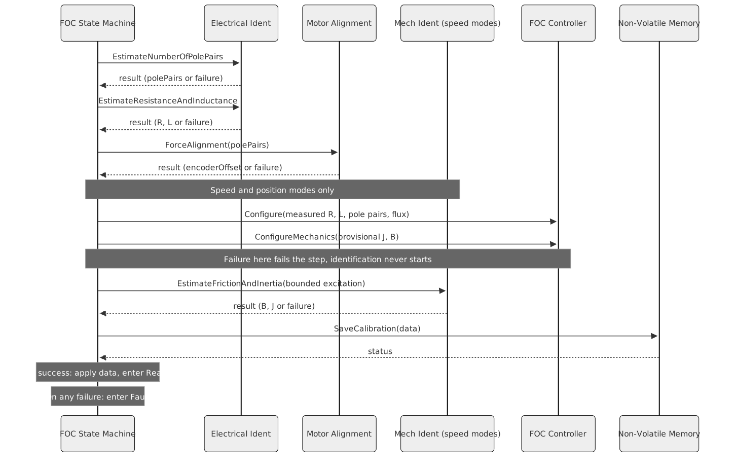
Steps and data produced:
| Step | Service | Data stored |
|---|---|---|
| 1. Pole pairs | Electrical Ident | polePairs |
| 2. Resistance and inductance | Electrical Ident | rPhase, lD, lQ |
| 3. Alignment | Motor Alignment | encoderZeroOffset |
| 4. Apply measured model + provisional plant | FOC controller | Nothing persisted; makes the loops able to move the rotor |
| 5. Mechanical parameters (speed/position only) | Mechanical Ident | inertia, frictionViscous,
speedLoopBandwidth |
| 6. NVM persist | Non-Volatile Memory | All of the above written to EEPROM |
After saving, calibration data is applied to the FOC controller
(current PID gains computed from R/L/bandwidth, velocity PID gains
applied for speed modes), and the state machine transitions to
Ready. The encoder zero offset is not written back to the
encoder at this point; it is established only by the alignment step
itself during the calibration sequence.
Every record handed to the NVM is traced first as
[SM] Calibration record: R=… L_mH=… p=… J_uNms2=… B_uNms=….
Inertia and viscous friction are traced in micro-units because the
tracer prints three decimals, which cannot show values around 1e-6 and
1e-5; the same convention applies to the [EST] lines and
the [SM] Applying mechanical estimates line below.
The calibration record line is what an external observer, the software-in-the-loop suite included, compares against the plant it configured.
The torque constant every mechanical consumer uses — the
identification service, the online inertia estimator and the speed-loop
gain design — is not configured per target. It is derived from the
record as \(K_t = \tfrac{3}{2} p
\psi_f\) (core/foc/math/TorqueConstant.hpp), the
factor the plant model itself applies.
A motor whose flux linkage is set with set_flux_linkage
therefore gets a consistent torque constant without a second number to
keep in step (REQ-SM-027).
Making the loops live before mechanical identification
Mechanical identification is the only calibration step that asks the drive to move: it commands a speed trajectory and identifies the plant from the motion that results. Every earlier step injects current into a stationary rotor and needs no closed loop at all.
Until a model is applied, the current loop holds inert gains — it is configured from resistance, inductance and pole pairs, none of which are known before the electrical steps run — and the speed loop holds a zero current envelope and no plant, so its controller refuses to produce a reference at all. Starting identification in that state commands a speed no rotor ever reaches: the regressor carries no excitation, the run reaches its timeout, and the calibration fails on hardware while passing against any test double that publishes samples on demand.
Before starting identification the state machine therefore applies, to the live controller:
- the electrical model it has just measured in this run — the pending resistance, inductance, pole-pair count and effective flux linkage, with the current-loop tunings that follow from them;
- a bounded provisional mechanical model — a small placeholder inertia, zero viscous friction and a deliberately low speed-loop bandwidth. It is a stand-in that lets the speed loop act within its current envelope, not a measurement, and it is never persisted or reported as calibration.
Both are checked. If the pending electrical record is not usable, if
the torque constant derived from the pending pole pairs and effective
flux linkage (\(K_t = \tfrac{3}{2} p
\psi_f\), the same factor the plant model applies) is not
positive, or if either configuration call is refused by the controller,
identification is not started: the step fails and the
machine enters Fault. A run that cannot move the rotor is a
failed calibration, not a run that silently produces nothing.
The excitation the service is given is bounded in current, speed and time. The current envelope is the drive’s own configured limit, with a small margin above it so that noise at the clamp does not read as a runaway, and the service clamps that down again to what the inverter reports it supports. The speed limit is derived from the commanded target rather than from any rated speed of the machine, because no per-drive speed rating is configured anywhere in the system; it bounds the trajectory against a runaway, not against a motor whose safe speed is below the commanded target.
Restoring the controller after an aborted run
The provisional model must not outlive the run that needed it. Every way a calibration can end short of a committed record reaches the same restore, because they all pass through the one place that aborts a calibration run: a failed step, a refused configuration, a failed NVM save, a hardware fault, an emergency stop, and the release of the machine’s external resources when it is torn down. A record that saves but is incomplete for this mode restores as well, since nothing was committed for the loops to keep.
| Situation | Restored state |
|---|---|
| A valid calibration is still held | That record is re-applied: electrical model, current tunings, mechanics, estimator seeds |
| No valid calibration is held | Nothing is re-applied; the motor stays un-enableable until a calibration succeeds |
A committed calibration supersedes the provisional model instead of restoring over it: the record just saved is applied in full, so there is nothing left to put back.
Validating the identified mechanics
An identified pair is accepted only when it is finite and inside the
physical band the mechanical identification service and the online
estimator share (see the Mechanical Parameters Identification design
document). A non-finite, non-positive or out-of-band inertia or friction
fails the step through the normal calibration-failure path —
CommandResult::calibrationFailed,
FaultCode::calibrationFailed, Fault — and is
never handed to the NVM service. The completeness check that stamps
CalibrationStage::complete catches zero and non-finite
values but not a merely absurd one such as an inertia of 10^30, which is
why the band is applied at the point the estimate arrives.
External Calibration (CAN-driven)
An external client (e.g. the CAN bridge) can supply pre-measured calibration data without running the internal identification chain. This uses a two-command protocol to ensure the FSM state is correct before any inverter interaction begins:
CmdReserveExternalCalibration()— synchronous. Checks that the machine is inIdleorReadywith no pending async work, like every command that starts asynchronous work, then transitions toCalibratingand returnsCommandResult::ok. ReturnsCommandResult::rejectedin any other state. TheCalibratingstate prevents a second request from being accepted concurrently.CmdCompleteExternalCalibration(data, onDone)— async. Called by the external client after its own estimation is finished. Storesdatain the pendingCalibratingslot and runs the alignment step, so an externally supplied record still gets a live rotor frame before it can be used. Its guard refuses the command while another command is still pending, so a second completion sent while the first is aligning is rejected instead of overwriting the pending record. If a fault occurred between the two calls, the machine is inFault, where the completion command has no row and is rejected; the client observes the failure through its own estimation callback.
The two-command split ensures the FSM enters Calibrating
before any open-loop PWM is applied, and that the state guard lives
entirely inside the state machine rather than in the calling layer.
The external path stops after alignment; it does not chain into
mechanical identification. OnIdentifyElectrical and
OnIdentifyMechanical are separate CAN commands
(REQ-INT-011), so the electrical command must not drive the mechanical
estimator. The NVM save therefore stamps stage = complete
only when the record satisfies the active mode’s own validity
requirements. Torque mode is satisfied by electrical parameters plus
alignment and transitions to Ready. Speed and position
still lack inertia and friction, so their record is persisted with
stage = none and the machine returns to Idle
holding a partial record, reported over CAN as
FocMotorState::partialCalibration. Completing those modes
requires the internal CmdCalibrate chain, which runs
mechanical identification.
Fault Safety
Event-dispatcher path. The
FaultDetected event has a row from every state to
Fault. Its action records the code, latches the fault
controller, stops the inverter if the machine was in
Enabled or Calibrating, and aborts the
calibration services; only then is Fault committed. Any
event raised while that happens, a further fault from inside the stop or
a calibration completion the abort could not suppress, is queued and
handled only after Fault has been committed, so it cannot
observe the state being left. A further fault does re-enter
Fault, but the recorded code is the one that first tripped
the drive: the fault raised while shutting down is a consequence, and
overwriting the root cause with it would lose the only diagnostic the
operator has. The new code is recorded again once the fault has been
cleared.
The clear budget is spent where the transition commits, not where the
command is issued. CmdClearFault only reads whether a clear
is still allowed; the row action is what consumes one of the three
attempts and releases the latch, so a ClearFault that is
queued and then refused does not silently cost an attempt.
Interrupt path (board protection, CAN bus-off). When
a fault is delivered in interrupt context, the platform stops the FOC
controller bridge immediately within that interrupt — before any state
mutation or tracing. The FaultDetected event, its trace
output and any pending-command completion are posted to the event
dispatcher and execute on the next dispatcher turn. This ensures no
multi-word state write, tracing call or non-volatile-memory access runs
from an interrupt context (see REQ-SM-021).
Stopping the inverter is not on its own enough to cut the PWM output.
The identification services drive the bridge through their own timers
and phase-current callbacks, and one left running writes duty cycles on
its next tick — ThreePhasePwmOutput re-arms the peripheral
that Stop() just disabled. So the transition to
Fault and CmdEmergencyStop both call
Abort() on the electrical identification, the alignment and
(in speed and position modes) the mechanical identification.
Abort() stops injection, cancels the service’s timers, and
drops the pending completion without invoking it: the
state machine owns the outcome, and a late calibration result must not
overwrite the fault that interrupted it. A service that has been aborted
or has completed ignores any further phase-current sample it is handed,
rather than reclaiming the inverter’s callback slot — reassigning that
slot from inside its own invocation would destroy the closure being
executed.
The Runner releases the inverter’s phase-current
callback in Disable() for the same reason: a callback left
pointing at a stopped control loop is another path back to
ThreePhasePwmOutput.
The transition to Enabled commits the state
before the FOC controller is started: the start runs as
a post-commit effect of the transition, and a fault raised while it runs
is queued behind it. A fault raised in the window where current first
flows would otherwise observe Ready, skip the stop, and
then be overwritten by the pending assignment to Enabled —
leaving an energised bridge on faulted hardware with the machine
reporting Enabled. Because the state is committed first,
such a fault stops the drive.
Committing the state first is not on its own enough for a fault
delivered from an interrupt, because that path dispatches
FaultDetected on the event dispatcher, not in the
interrupt: reading the lifecycle state around the start would still see
Enabled. The latch is therefore set in the
interrupt, and the Enabled entry hook consults the
latch rather than the state — before Start(), so the cutoff
the interrupt performed is not undone, and again after it, for a fault
raised while Start() ran. Either check turns the latched
fault into a FaultDetected dispatch, which the table queues
and drains before the Enable dispatch returns; the whole
enable sequence is therefore atomic with respect to the fault and
CmdEnable reports abortedByFault.
The same reasoning applies one level down, inside
Runner::Enable(). Its steps — take the phase-current slot,
enable the control law, start the inverter, set the enabled
flag — are individually interruptible, and a Stop() from
the faulting context between any two of them would be undone by the
steps that follow it, re-arming the bridge on hardware that has just
faulted, with no control loop attached to update it.
Enable() therefore clears a stopRequested flag
that Disable() sets, re-checks it after every step, and
unwinds through Disable() once it is set. A stop landing
after the last check needs no unwinding: it runs after every write the
sequence makes. The flag is written from the faulting context as well as
the mainline, so it is set and cleared outright rather than counted — a
read-modify-write shared with an interrupt is exactly what REQ-SM-021
excludes.
Fault Latching
A fault is latched. CmdEnable is refused while the latch
is set, so the only path out of Fault is an explicit
CmdClearFault.
Clearing is gated twice: on the hardware condition, and on a retry
budget. FaultController::EvaluateClear() reports the first
gate that refuses, condition before budget, so the operator is told the
physical cause rather than the accounting.
The condition gate.
PlatformFactory::BoardProtectionStatus() reports
asserted, clear or unknown. While
a fault is held, FaultController polls it every
conditionPollInterval (50 ms) on the event dispatcher — on
its own schedule rather than only when a command arrives, because a
condition that asserts and clears between two operator commands would
otherwise never be observed as asserted at all. A clear is accepted only
once the condition has been seen to leave asserted and to
have stayed clear for conditionDwell (250 ms);
the dwell is stamped on the asserted → clear transition, so
any asserted sample inside the window restarts it and a condition
chattering around its threshold cannot be cleared on one favourable
reading. IsEnableAllowed refuses independently while the
condition reads asserted, so a clear granted during a
momentary deassertion still cannot arm the bridge.
  asserted ──clear sample──> settling ──dwell elapsed──> ready ──CmdClearFault──> cleared
      ^                          │
      └────asserted sample───────┘
unknown is the honest answer from a platform that cannot
interrogate its protection hardware, and it neither blocks a clear nor
satisfies the verification — such a platform behaves exactly as it did
before the gate existed. Reporting clear instead would
assert a verification the hardware never made, and a fault on those
platforms comes from software (calibration failure, CAN bus-off,
watchdog) rather than from a physical condition anything could hold.
Every platform reports unknown today: the
TI protection comparators are ADC digital comparators on a PWM-triggered
ADC, which stops converting once the bridge is stopped, so no reading
taken while faulted distinguishes a cleared condition from an
unevaluated one. The gate is in place and tested, and becomes
load-bearing as soon as a platform can answer — see REQ-EH-013.
The budget. Each accepted CmdClearFault
increments a counter; once maxConsecutiveFaultClears (3)
clears have happened without an intervening clean run, further clears
are refused and a reset is required. The counter is reset by
CmdDisable from Enabled, which is the only
evidence the state machine has that the drive ran and was stopped
deliberately rather than by the same condition re-tripping. The budget
supplements the condition gate rather than replacing it: it bounds the
platforms that cannot verify, and it bounds a condition that happens to
read clear between attempts on those that can. A clear the condition
refused does not spend from it.
FaultController::Clear() asserts on the budget alone. It
runs where the transition commits, not where the command was issued, and
a condition that re-asserts in that window must refuse the clear —
asserting on it there would reset a board whose hardware is still
faulted, turning a fault into a reset loop.
The last fault code is preserved in LastFaultCode() and
remains readable even after the fault is cleared via
CmdClearFault. Before any fault has occurred it reads
FaultCode::none, so a client can distinguish “no fault yet”
from a real hardware fault.
Faults raised in interrupt context
PlatformFaultNotifier’s primary path runs in the PWM
fault interrupt (board protection) or the CAN interrupt (bus-off).
Neither is a context in which the transition itself can be taken: the
transition to Fault traces, writes a multi-word
std::variant that the CLI and the CAN bridge read
concurrently, and completes a pending command that reaches non-volatile
memory.
The split is therefore: latch and cut the bridge in the
interrupt, record the fault in the dispatcher. The registered
handler latches the fault and calls Stop() on the FOC
controller synchronously — unconditionally, without consulting the
state, because hardware saying “fault” outranks the state machine’s
belief about what it was doing — and then hands the
FaultDetected event to infra::EventDispatcher.
The secondary handler, which broadcasts the fault over CAN, already
worked this way.
Latching is three single-word writes (pendingCode,
faultPending, faultLatched), which is all an
interrupt may do here: the tracing, the multi-word
std::variant write and the pending-command completion stay
on the dispatcher. faultLatched says a fault is in force
and is what commands consult; faultPending says the
FaultDetected transition it owes has not been taken yet,
and is consumed by whichever context takes it.
FaultController keeps a third, dispatcher-only flag,
faultRecorded, for “the transition has been taken” — the
distinction faultLatched carried before latching moved into
the interrupt, and what decides whether an arriving fault is the one
that tripped the drive or a further one whose code is kept out of
LastFaultCode().
TakePendingFault() claims the flag and the code together
and hands back the code, so a second interrupt landing mid-claim cannot
leave the taker dispatching one fault’s transition under another’s code.
Claiming is the only thing that clears
faultPending: taking the transition does not, or a fault
latched while that transition ran would be wiped before its own
dispatcher turn reached it and would never be recorded at all. For the
same reason CmdClearFault is refused while a fault is
pending — clearing there would drop the latch of a fault that has
already tripped the drive, and spend one of the three permitted clears
on a state the next dispatcher turn immediately undoes. A fault whose
transition is still owed also counts as pending asynchronous work, which
is what stops a control-mode switch from destroying the state machine —
and with it the latch and the queued FaultDetected — in
that window.
A consequence worth knowing when reading the code or the tests:
between the interrupt and the dispatcher turn, the bridge is off and the
latch is set, but CurrentState() still reports the
pre-fault state. Commands consult the latch, not the state, so an enable
arriving in that window is refused rather than acted on. The transition
is taken exactly once — whichever of the dispatcher turn or the enable
sequence reaches it first takes the pending fault, and the other finds
nothing left to record.
Registration lifetime
A FaultNotifier outlives the state machines that
register with it — a control-mode switch destroys one state machine and
constructs the next in the same std::variant — so each
state machine releases its registration and aborts its calibration
services in its destructor. Without that, the notifier’s
infra::Function and the services’ pending callbacks both
point into freed storage.
Hardware protection events reach the state machine through
PlatformFaultNotifier, the production
FaultNotifier. It registers a callback with
PlatformFactory::RegisterBoardProtection() during
construction and translates each BoardProtectionReason into
the matching FaultCode:
BoardProtectionReason |
FaultCode |
|---|---|
overCurrent |
overcurrent |
overVoltage |
overvoltage |
underVoltage |
undervoltage |
overTemperature |
overtemperature |
A protection event raised before the state machine has registered its handler is discarded by the state machine. A platform whose protection reflects a standing condition rather than an edge is expected to re-raise it once a handler exists, so a motor does not enable into a condition the board had already detected.
Async-Callback State Invariant
A hardware fault, an operator command, or a second calibration attempt may move the state machine between the moment a service call is issued and the moment its callback fires. The invariant is: a callback may only apply its result if the state machine is still in the state that issued the service call.
This invariant is no longer a convention that every callback re-implements. Each callback translates its result into an event and dispatches it; whether the result is applied is decided by the transition table:
- Results from calibration steps
(
EstimateNumberOfPolePairs,EstimateResistanceAndInductance,ForceAlignment,EstimateFrictionAndInertia) become the eventsCalibrationStepChanged,AlignmentSucceeded,MechanicalParametersIdentifiedandCalibrationStepFailed, which only have rows inCalibrating. The mechanical result additionally carries a guard on the active sub-step. The calibration orchestrator also drops results of a run that was aborted. - The
SaveCalibrationcompletion becomesCalibrationSaved, which only has rows inCalibrating, and only ever carries a non-Busystatus:CalibrationFlowretries aBusyresponse internally (see C2c) rather than dispatching it. The callback also carries the epoch of the transition that issued the save, so a save completing after an emergency stop and a freshCmdCalibrateis discarded instead of being consumed by the new run. - The boot-time NVM completions become
BootValidityCheckedandBootCalibrationLoaded, which only have rows inIdle. - The
InvalidateCalibrationcompletion becomesCalibrationInvalidated, with rows inIdleandReady, leading toIdleon success, toFaulton failure, and completing the command withrejectedwhen the NVM is busy. It needs no request identity: the guard on every command that starts NVM work means one invalidation at most is outstanding. - The flux-linkage save completion becomes
FluxLinkageSaved, handled inIdleandReadyand completing the pending command without a transition. - Both NVM completions also have rows in
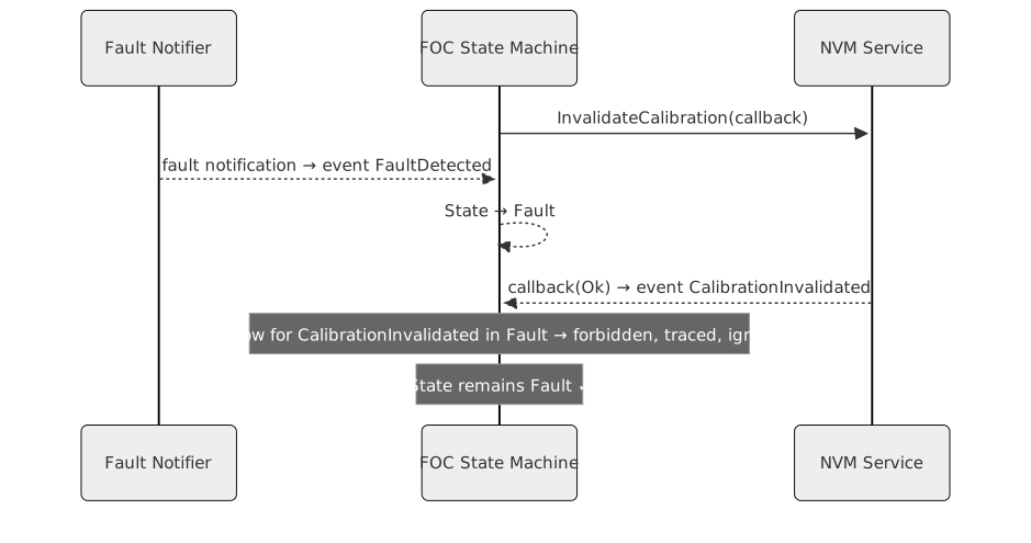
Fault, because a fault or an emergency stop while the operation is in flight aborts the command but not the erase or the write. The RAM record follows the NVM outcome whatever happened to the command: a successful invalidation drops the record, so a laterCmdClearFaultreturns toIdlerather than restoring a calibration that no longer exists in NVM, and a stored flux linkage is applied. An invalidation that fails while already inFaultis ignored; the fault is already latched.
Any of these events arriving in a state without a row for it is
forbidden, and the save completion arriving after a
transition is discarded before it reaches the table.
Either way it is traced, and it never overwrites a later state such as
Enabled or Fault with a stale result.
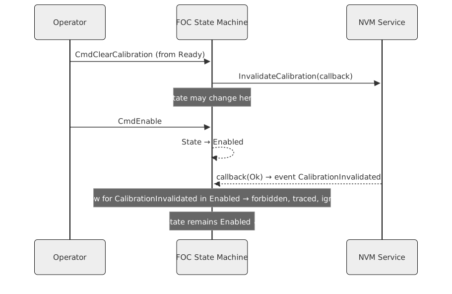
A matching race with a hardware fault that arrives between the
CmdClearCalibration call and the
InvalidateCalibration callback:
Transition Policies
Each state machine instance is constructed with a transition policy that only decides whether the lifecycle commands appear on the terminal:
- CLI policy: the commands
calibrate,align,enable,disable,clear_faultandclear_calare registered on the connected terminal. Used by the state machine unit tests and for commissioning over a serial console. - Automatic policy: no terminal commands are
registered. The caller drives transitions programmatically, for example
from CAN message handlers. This is the policy the
ControlModeStateMachineuses for the torque, speed and position machines it owns.
Both policies share the same transition table; they differ only in whether lifecycle commands appear on the terminal.
Mechanical Identification and Control Mode
The calibration sequence extends with a mechanical identification step for speed and position control modes. This step estimates rotor inertia and viscous friction, then computes initial velocity-loop PID gains.
For both speed and position mode, the mechanical
identification service is constructed by
OuterLoopStateMachine::ResolveMechIdent when no external
override is supplied in CalibrationServices. The two modes
share that path; position mode does not require an override and does not
fail calibration for the lack of one. An override is a test and
integration seam, not a configuration requirement.
Boot-Time NVM Check
On construction, the state machine asynchronously checks whether
valid calibration data exists in NVM. If data is found and loads
successfully, the electrical parameters (R, L, pole pairs, current-loop
bandwidth) are applied to the FOC controller, but the machine
remains in Idle — the rotor-reference
(encoder zero offset) is RAM-only and is lost on every reset, so it must
be re-established by a live alignment before the motor can be enabled.
If the check fails or the data is absent, the machine starts in
Idle with no parameters applied.
Alignment-Only Recovery
CmdReAlign() re-establishes the rotor reference without
re-running the full identification chain. It requires the machine to be
in Idle or Ready with valid electrical
calibration already loaded (non-zero pole pairs and positive phase
resistance). The procedure:
- Enters
Calibratingat the alignment sub-step, copying the stored electrical parameters intopendingData. - Calls the Motor Alignment service using the stored pole pairs.
- On success: marks
rotorReferenceValid, saves the updated offset to NVM through the same completion path as a full calibration, applies mode-specific calibration from the stored parameters, and transitions toReady. - On failure: enters
Faultwith codecalibrationFailed.
The CLI command is align (short form aln).
Because the same completion path is used, the speed and position loop
parameters are also re-applied from the stored calibration, so
mechanical identification does not need to be re-run after an
alignment-only recovery.
Online Parameter Estimation (Speed/Position Modes)
For speed and position control modes, the state machine creates and manages two online parameter estimators alongside the main control loop:
- Online Mechanical Estimator — continuously refines rotor inertia (J) and viscous friction (B) using a Recursive Least Squares estimator that runs at the outer-loop rate (1 kHz).
- Online Electrical Estimator — continuously refines phase resistance (R) and d-axis inductance (Ld) using a d-axis voltage-model RLS estimator running at the same rate.
Lifecycle of online estimators:
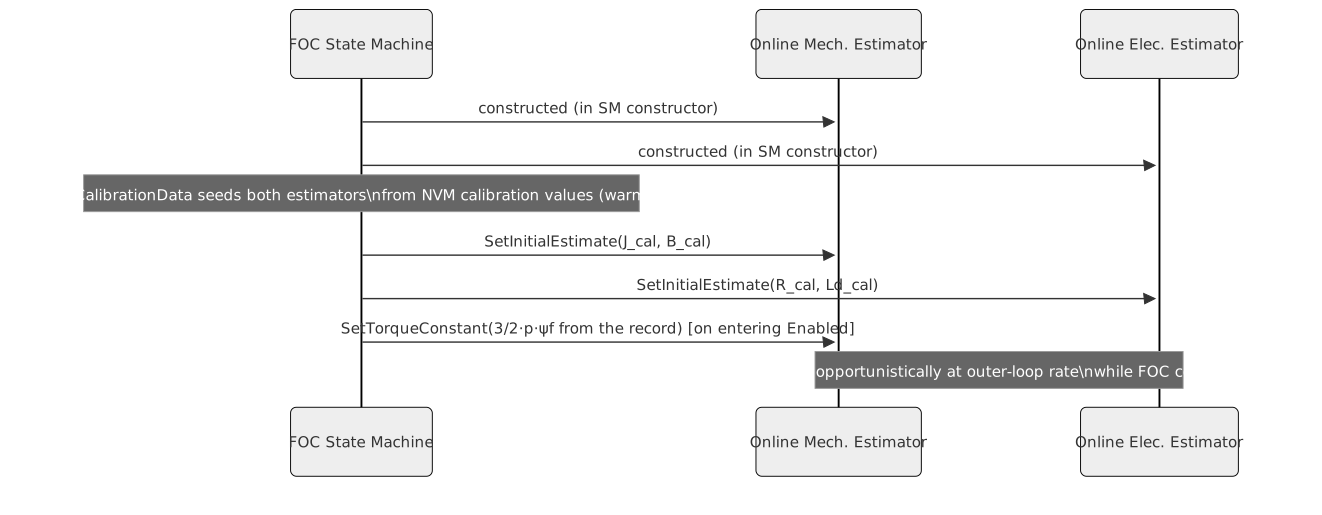
Seeding from calibration data: When
ApplyCalibrationData is called (either after calibration
completes or on NVM boot load), both estimators are seeded with the
values from CalibrationData. This warm-starts the RLS theta
vector at the known-good calibration values rather than zero, ensuring
the estimators produce physically meaningful outputs from the first
update.
The electrical estimator is seeded using lD (d-axis
inductance), as the underlying model assumes a non-salient motor (\(L_d \approx L_q\)). For interior PMSMs, a
3-parameter model with separate Ld and Lq would be required; this is a
known limitation.
Estimate consumption is explicit: Estimates are NOT
applied to PID gains continuously. The operator (or application logic)
explicitly triggers a PID retune by calling
ApplyOnlineEstimates(). This prevents gain oscillation
before the estimators have converged and guards against applying
poorly-conditioned estimates at runtime.
When ApplyOnlineEstimates() is called while in
Enabled state: 1. Current inertia and friction estimates
are read from the mechanical estimator 2. Speed PID gains are recomputed
using the bandwidth-based rule from
documentation/theory/speed-loop-pi.md (“What the
implementation uses”): \(k_p = 2 J \omega_{bw}
/ K_t\), \(k_i = k_p \max(B_f/J,\
\omega_{bw}/4)\, T_s\) with \(T_s\) the outer-loop sample period, where
\(J\) is the estimated inertia, \(B_f\) the viscous friction, and \(K_t = \tfrac{3}{2} p \psi_f\) the torque
constant derived from the calibration record 3. Current resistance and
inductance estimates are read from the electrical estimator 4. Current
PID gains are recomputed from the bandwidth-based tuning rule
If called from any state other than Enabled, the call is
silently ignored.
Runtime control commands (CLI policy, speed/position modes only):
| Command | Short | Description |
|---|---|---|
apply_estimates |
ae |
Apply online estimates to speed and current PID gains |
estimate_status |
es |
Print current J, B (micro-units), R, Ld to the tracer |
Control Mode
Selection (ControlModeStateMachine)
ControlModeStateMachine is a higher-level coordinator
that owns one FocStateMachineCommon subclass per supported
control mode (TorqueStateMachine,
SpeedStateMachine, PositionStateMachine), held
in a std::variant. At any given time exactly one mode’s
state machine is the active instance; the others are
idle. This section documents three behavioral invariants introduced to
make runtime mode switching safe and predictable.
C1 — CAN Wire-Scale Convention
ControlModeStateMachine receives setpoints from the CAN
bridge in physical unit types (foc::Ampere,
foc::RadiansPerSecond, foc::Radians). The
fixed-point wire encoding (scale constants in
core/can/FocMotorMessages.hpp, round-to-nearest with
saturation) is specified once, in
documentation/design/service-can.md Part A.
C2 — Re-entrancy Guard for In-Flight Selection
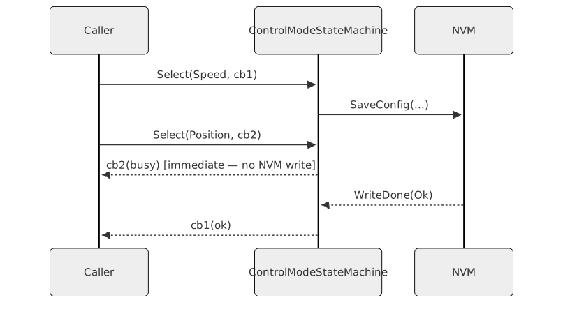
Switching control mode involves an asynchronous NVM write to persist
the new default. A second Select() call issued while this
write is still outstanding must not be applied until the first operation
completes, since the NVM driver does not support concurrent write
requests.
Behavioral rule: if a Select() is called while a
previous Select() callback has not yet fired, the call
returns SelectResult::busy immediately and takes no other
action. The caller is responsible for retrying.
The same guard covers the active mode’s own asynchronous work.
Applying a selection destroys the active
FocStateMachineCommon instance, while its outstanding NVM
and identification callbacks still capture that instance.
Select() therefore also returns
SelectResult::busy when
ActiveStateMachine().HasPendingAsyncWork() is true — that
is, while a command callback is pending, any NVM operation is in flight,
a calibration step is running, or a fault latched in an interrupt still
owes its transition — in addition to the existing check that the active
machine is stopped. Without that last condition the machine, its latch
and the queued transition would all be destroyed in the window between
the interrupt and the dispatcher turn, and the machine built in its
place would start unlatched. NvmActivity counts every NVM
operation from the call until its callback, so a save or invalidation
still outstanding after an emergency stop keeps the machine alive until
it completes.
C2a —
One NvmActivity for Every Writer of the Shared NVM
NonVolatileMemoryImpl serves one operation at a time and
answers a concurrent call with Busy, without queueing.
NvmActivity is therefore owned by
ControlModeStateMachine, which outlives every mode switch,
and every writer of the shared instance brackets its operation with
it:
| Writer | Accounting |
|---|---|
Calibration, maintenance and boot (CalibrationFlow,
MaintenanceFlow, BootSequence) |
LifecycleEnvironment::nvmActivity, a reference to the
shared counter |
Select’s SaveConfig and its rollback
write |
Begin/End around each write |
AlgorithmPersistence::PersistConfig |
Begin before the first attempt, End once a
status other than Busy arrives |
FocMotorCanBridge encoder-resolution and telemetry-rate
writes |
ControlModeStateMachine::BeginNvmActivity/EndNvmActivity |
HasPendingAsyncWork() is therefore true while any of
them is outstanding, and every guard built on it —
CmdCalibrate, CmdEnable,
CmdClearCalibration, Select — refuses instead
of colliding.
C2b — Algorithm Selection Is Refused While Busy
SelectCurrentAlgorithm,
SelectSpeedAlgorithm and
SelectPositionAlgorithm apply the same guard as
Select — the active machine is Idle or
Ready and has no pending asynchronous work — and return
busy otherwise. Selection is therefore refused while
Calibrating, Enabled or Fault,
and while any NVM operation is outstanding. The cascades’ own refusal
while enabled remains as a second guard.
C2c — A Busy Calibration Save Is Retried
CalibrationFlow retries a SaveCalibration
answered with Busy every 10 ms from a copy of the record,
keeping NvmActivity raised and reusing the completion
captured at the epoch of the run, so CalibrationSaved is
only dispatched with the status of a write that actually ran. An abort
while a retry is waiting cancels it and releases
NvmActivity: an aborted run is not persisted.
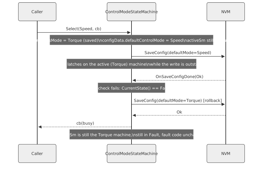
C3 — Deferred Apply and Re-check Before Activate
Select() does not switch the active state machine up
front. It records the previous defaultControlMode, writes
the new one into configData and starts the asynchronous
SaveConfig; activeSm is untouched until
OnSaveConfigDone runs.
Select() starts the write only when the active machine
is stopped and has no pending asynchronous work, but that is a snapshot:
a fault, an emergency stop or a calibration can land while the write is
outstanding. Activating the new mode then would destroy the machine that
holds the fault and start the new one unlatched.
OnSaveConfigDone therefore decides:
- Write failed: restore
configData.defaultControlMode(NVM still holds the previous default) and reportbusyfor a transient failure ornvmFailedotherwise. The active mode was never touched. - Write succeeded and the guard still holds:
Activate(pendingSelectMode)and reportok. - Write succeeded but the guard no longer holds: keep
the active mode, restore
configData.defaultControlModeand write it back so NVM agrees with the running mode, then reportbusywhen that write completes, whatever its status. The pending callback stays set during the rollback write, so aSelect()in that window is refused withbusy(C2).
Interfaces
Provided
| Interface | Purpose | Contract |
|---|---|---|
FocStateMachineBase |
Abstract lifecycle controller — state query and command dispatch | Constructed once per application; all command methods are safe to call from any state (a command without a row in the current state is rejected with a status and traced, never applied) |
CurrentState() |
Returns the current State variant for inspection |
Returns a const reference; valid for the lifetime of the state machine |
LastFaultCode() |
Returns the most recent fault code | Returns FaultCode::none until the first fault occurs;
afterwards it retains the last fault code, also after the fault is
cleared |
CmdCalibrate() |
Requests start of full calibration sequence | Only effective from Idle or Ready; ignored
from all other states |
CmdReAlign() |
Re-establishes the rotor reference without re-running R/L or mechanical identification | Only effective from Idle or Ready with
valid electrical calibration loaded; enters Calibrating
(alignment sub-step only), then Ready with
rotorReferenceValid on success, or Fault on
failure |
CmdEnable() |
Requests enabling the FOC controller | Only effective from Ready when
rotorReferenceValid is true; rejected when the rotor
reference has not been established since the last reset |
CmdDisable() |
Requests disabling the FOC controller | Only effective from Enabled; ignored from all other
states |
CmdClearFault() |
Clears the fault and returns to Ready if valid
calibration is held, otherwise Idle |
Only effective from Fault; ignored from all other
states |
CmdClearCalibration() |
Invalidates NVM calibration and returns to Idle |
Only effective from Idle or Ready; ignored
from Calibrating, Enabled, and
Fault. On NVM failure transitions to
Fault. |
CmdEmergencyStop() |
Stops PWM immediately and leaves the active states | Accepted from every state and always returns ok. From
Enabled or Calibrating it goes to
Ready when calibration data is valid, otherwise to
Idle. Idle, Ready and
Fault are left unchanged. Aborts any pending command with
abortedByFault. |
HasPendingAsyncWork() |
Reports whether a service callback capturing the machine is outstanding | True while a command callback is pending, any NVM operation is in
flight, a calibration step is running, or a fault latched in an
interrupt still owes its transition. Used by
ControlModeStateMachine to refuse destroying the
machine. |
HasPartialCalibration() |
Reports whether Idle holds a non-empty but incomplete
NVM record |
True only in Idle, when stage != complete
but pole pairs or resistance are non-zero (an old-schema or interrupted
record). Used by the CAN bridge to broadcast
FocMotorState::partialCalibration instead of
idle. |
ApplyOnlineEstimates() |
Retunes speed and current PID gains from online estimators | Only effective from Enabled; silently ignored from all
other states. Skips non-physical estimates (non-finite or <= 0).
Speed/position modes only. |
Required
| Interface | Purpose | Contract |
|---|---|---|
NonVolatileMemory |
Persists and retrieves calibration data across power cycles | Must remain valid for the lifetime of the state machine |
ElectricalParametersIdentification |
Estimates pole pairs, phase resistance, and dq inductances | Operations are asynchronous; callback fires on the same event loop |
MotorAlignment |
Forces rotor to a known angle and returns the encoder zero offset | Operation is asynchronous; result is optional (nullopt = failure) |
MechanicalParametersIdentification |
Estimates rotor inertia and viscous friction (speed/position modes only) | Operation is asynchronous; result is optional (nullopt = failure) |
FaultNotifier |
Delivers hardware fault notifications to the state machine | Register() must be called during construction; callback
may fire at any time. Production implementation is
PlatformFaultNotifier. |
ThreePhaseInverter |
Used by the FOC controller to issue PWM and read phase currents | Stopped immediately on any fault from Enabled or
Calibrating state |
Encoder |
Rotor position sensor; zero point established by the alignment step | Read-only from the state machine’s perspective;
SetZero() is called by MotorAlignment during
calibration, never by the state machine itself |
TerminalWithStorage |
Serial command interface for CLI-mode transition policy | Commands registered in constructor; terminal must outlive the state machine |
Tracer |
Debug trace output for lifecycle events | All state transitions and calibration steps are traced |
RealTimeFrictionAndInertiaEstimator |
Online RLS estimator for rotor inertia and viscous friction (speed/position only) | Seeded from calibration data; torque constant 3/2·p·ψf from the
record set on entering Enabled; updates run while FOC outer
loop is active |
RealTimeResistanceAndInductanceEstimator |
Online RLS estimator for phase resistance and d-axis inductance (speed/position only) | Assumes non-salient motor (Ld ≈ Lq); seeded using lD
from calibration |
Data Model
| Entity | Field | Type / Unit | Range | Notes |
|---|---|---|---|---|
CalibrationData |
polePairs |
count (uint8) | 1–255 | Number of electrical pole pairs |
CalibrationData |
rPhase |
Ohm (float) | > 0 | Phase resistance identified by electrical ident |
CalibrationData |
lD / lQ |
mH (float) | > 0 | D/Q inductances (set equal; anisotropy not estimated) |
CalibrationData |
encoderZeroOffset |
int32 (bit-cast float Radians) | any | Mechanical angle at encoder zero when rotor settled during alignment; stored for reference only — not re-applied to the encoder at boot or after calibration (see REQ-SM-019) |
CalibrationData |
inertia |
N·m·s² (float) | ≥ 0 | Rotor inertia; populated only for speed/position modes |
CalibrationData |
frictionViscous |
N·m·s/rad (float) | ≥ 0 | Viscous friction coefficient; populated only for speed/position modes |
CalibrationData |
frictionCoulomb |
N·m (float) | ≥ 0 | Coulomb friction; currently 0 (not identified) |
CalibrationData |
speedLoopBandwidth |
rad/s (float) | ≥ 0 | Speed loop closed-loop bandwidth; populated only for speed/position modes |
CalibrationData |
currentLoopBandwidth |
rad/s (float) | ≥ 0 | Current loop closed-loop bandwidth; defaults to 2π·fs/nyquistFactor when zero |
FaultCode |
— | enum (uint8) | 8 values | overcurrent, overvoltage,
undervoltage, overtemperature,
encoderLoss, watchdogTimeout,
hardwareFault, calibrationFailed |
watchdogTimeout is reserved and not raised by the state
machine. A watchdog expiry cuts the power stage from the watchdog
interrupt and the hardware resets the target, so there is no dispatcher
turn in which a latched fault code could be read or broadcast; the
expiry is reported after reboot through
ResetCause::watchdog instead. The watchdog does not reach
the state machine at all. See Watchdog
Design.
Error Handling
All calibration steps produce std::optional results. A
nullopt from any step immediately enters Fault
with code calibrationFailed. The entire calibration
sequence is safe to retry by issuing CmdCalibrate after
CmdClearFault.
NVM operations (save, load, invalidate) are also asynchronous and
report a NvmStatus. On any non-Ok status
during save or load, the machine enters Fault or remains in
Idle, respectively, without corrupting application
state.