e-foc System Architecture
| Field | Value |
|---|---|
| Title | e-foc System Architecture |
| Type | architecture |
| Status | draft |
| Version | 0.1.0 |
| Component | system |
| Date | 2026-04-07 |
Note — Architecture-level document: This document describes what the system is and why it is structured this way. Code must follow the architecture, not the opposite. Logical component and interface names are the vocabulary of architecture and belong here. What must be avoided: source file paths, implementation class names (e.g.
FooImpl), and code-level algorithmic details.Diagrams: All visuals must be either a Mermaid fenced code block or ASCII art inline in the document. External image references (
) are not allowed.Sequence diagrams, block diagrams, component diagrams, and state machines (Mermaid syntax) are allowed and encouraged.
Assumptions & Constraints
- Constraint: No dynamic memory allocation on the embedded target. All objects are stack- or statically-allocated for deterministic, bounded memory footprint.
- Constraint: The core FOC loop executes in an interrupt service routine at 20 kHz. The complete control cycle must not exceed 75 percent of the available CPU time per control period (<= 4500 cycles at 120 MHz / 20 kHz) to guarantee real-time deadlines.
- Constraint: No recursion in control-loop or ISR-reachable paths. Stack usage must be statically predictable.
- Constraint: No C++ exceptions. Error signalling
uses status return values,
std::optional, or asynchronous callbacks. - Constraint: The system targets 32-bit ARM Cortex-M microcontrollers (STM32 and TI Tiva families). Host builds are supported for unit testing and simulation only.
- Assumption: A single motor is controlled per instantiation. Multi-motor configurations require multiple independent instantiations.
- Assumption: The motor is a BLDC or PMSM (surface or interior permanent magnet) with a sinusoidal back-EMF profile suitable for FOC.
- Assumption: Rotor position is measured by a quadrature encoder. Hall-sensor support is defined in the driver interface but is a secondary configuration.
- Assumption: All motor electrical and mechanical parameters (resistance, inductance, pole pairs, inertia, friction) can be identified at startup or loaded from non-volatile storage.
- Constraint: The build system produces a single
unified binary (
e_foc.sync_foc_sensored.main) that contains all three control modes. The active mode can be selected at runtime via CAN command (SelectControlMode) and persisted to NVM so it survives a power cycle. The CLI commandactive_modereports the currently active mode. No mode switch is permitted while the motor is enabled.
System Overview
e-foc is a Field-Oriented Control (FOC) firmware for BLDC and PMSM motors. Its purpose is to transform three-phase stator currents into a rotating reference frame so that torque and flux can be regulated independently with standard linear PIDs, then synthesise the three-phase PWM voltages via Space Vector Modulation.
The system is structured in four tiers:
- Infrastructure tier — external repositories providing general-purpose utilities, numerical algorithms, and vendor HAL drivers. These are consumed as submodules and are never modified by this project.
- Core / Library tier — the FOC algorithm library
(
core/foc/), service library (core/services/), and the Platform Abstraction Layer interface (core/platform_abstraction/). These are pure, portable libraries with no target-specific knowledge. - Targets tier — target-specific code that is NOT
reusable across all environments: platform implementations (concrete
PlatformFactoryfor TI, ST, and Host) and application entry points (hardware_test,sync_foc_sensored). Lives undertargets/. - Tools tier — host-only desktop tools (simulator,
CAN commander) that run on development machines only. Lives under
tools/.

The simulator implements the same PAL contracts as real hardware. Control logic never needs to distinguish between running on a microcontroller or on the host; this enables full-fidelity closed-loop validation without hardware.
Component Decomposition
1. FOC Core
The heart of the system. Decomposed into sub-layers following a strict separation of vocabulary, generic numerics, transform algorithms, orchestration, and wiring. Dependencies flow in one direction only — from wiring down towards vocabulary; no lower layer may depend on a higher one:
| Sub-component | Responsibility |
|---|---|
| Interfaces | Define the FOC vocabulary (units, phase and frame signal types) and the abstract contracts for control modes (Torque, Speed, Position) and execution (low-priority interrupt, controllable). No algorithms. Hardware ports live in the platform abstraction layer, not here. |
| Math | Generic numerical helpers that are not specific to field-oriented control — fast trigonometry by lookup table, angle wrap-around. Header-only, dependency-free. |
| Transforms | The field-oriented control mathematics proper: the Clarke and Park transforms in both directions, and Space Vector Modulation. |
| Loop algorithms | Interchangeable control laws for each loop, under
current_loop/, speed_loop/ and
position_loop/, together with their plant models and gain
design. |
| Selection | The ControllerSelector template that stores the active
algorithm of a loop in a fixed-size std::variant and
dispatches to it without allocation. |
| Cascade | Orchestration of the control cascade — the per-mode control loops that combine the current, speed and position algorithms. |
| Instantiations | Wiring that combines a control-mode cascade with the execution runner to produce a ready-to-use FOC controller. |
Because Interfaces, Math, and Transforms carry no dependency on the control cascade, the identification, alignment, and simulation components consume them directly without pulling in the control loops.
The three control modes are available in the same binary and are
selected at runtime through ControlModeStateMachine. Only
one mode is active at a time; switching is only permitted from
Idle or Ready state and persists the new
choice to NVM via defaultControlMode:
- Torque control — innermost loop: regulates phase currents to produce a commanded torque (specified as Id/Iq current setpoints).
- Speed control — outer loop on top of torque control: a PID regulates rotor angular velocity by commanding Id/Iq setpoints to the inner loop. The outer loop runs at a lower priority interrupt (typically 1 kHz) while the inner loop still runs at 20 kHz.
- Position control — outermost cascade: a PID regulates rotor position by commanding a speed setpoint to the speed loop. Builds on speed control.
Interrupt Priority Plan
On Cortex-M, equal priority means no preemption: a handler at the same level as the FOC ISR cannot be interrupted by it, so the FOC loop’s worst-case latency is the duration of the longest other handler at or above its level. Leaving every source at the default therefore leaves the 20 kHz deadline hostage to a CAN receive or a UART DMA completion.
The TI target assigns priorities explicitly in
application::InterruptPriorities:
| Source | Priority | Rationale |
|---|---|---|
| Phase-current ADC | highest |
Carries the 20 kHz control deadline; must preempt everything else |
| PWM fault | highest |
Hardware overcurrent/overvoltage trip; nothing may delay the response |
| CAN | normal |
Command and telemetry traffic; may be preempted by the control loop |
| UART | low |
Terminal and tracing; the least time-critical source on the board |
| PendSV (outer loop) | lowest |
Set by hal::cortex::LowPriorityInterrupt; the 1 kHz
outer loop must never preempt the current loop |
The outer loop runs on PendSV at the lowest configurable priority. It carries a 20 000-cycle budget against the inner loop’s 4 500, so running it above the current loop would insert up to a full outer-loop execution of duty-update jitter once per millisecond.

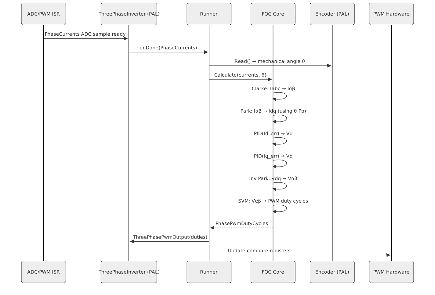
The Runner is the only component that interacts with the
PAL inverter and encoder at interrupt time. It registers the
ADC-sampling callback and drives the Calculate() dispatch
into the active control-mode implementation.
The dispatch carries no validation of the sample. Nothing in the 20
kHz path inspects the phase currents for plausibility or for finiteness:
at 4500 cycles a frame the budget is spent on the control law, and a
failed shunt or ADC channel is the hardware’s fault detection to catch,
not the control loop’s. foc::ToDutyCycles clamps each
modulator output into [0, 1] and converts to percent, and does nothing
else.
foc::IsFiniteValue survives for the places where
validation is affordable and worth having —
CurrentPlantModel::IsUsable when the plant is configured,
and the plausibility band the mechanical estimator applies before
publishing. Both run outside the hot path. It tests the float’s exponent
bits rather than calling std::isnan, which
-ffinite-math-only licenses the compiler to fold to a
constant; the embedded builds keep -fno-finite-math-only,
but the check does not depend on it.
2. Services
Higher-level, non-real-time services that support commissioning and runtime operation. Each service is independently usable:
| Service | Responsibility |
|---|---|
| Alignment | Forces a known electrical angle on the rotor at startup so the FOC reference frame is correctly initialised before normal operation. |
| Electrical System Identification | Estimates phase resistance, d/q inductances, and pole pairs by injecting test signals and measuring the response. |
| Mechanical System Identification | Estimates rotor inertia and viscous friction coefficient from closed-loop speed response data. |
| Non-Volatile Memory (NVM) | Persists calibration data (R, L, pole pairs, encoder offset, PID
gains) and configuration (including defaultControlMode)
across power cycles. |
| CLI | A terminal-based command interface for triggering services, querying state, and setting parameters from a serial console. |
| Control Mode | Owns the three FocStateMachine instances (torque,
speed, position) as a std::variant; only one is live at a
time. Exposes Select(mode, onDone) which enforces the
motor-stopped precondition, persists the selection to NVM, then switches
the active state machine. |
3. CAN Service
The CAN service layer (core/can/) provides the FOC motor
CAN category as a server/client pair and the bridge that connects the
server to the ControlModeStateMachine. It is split into two
halves:
Server half (runs on the embedded target): -
FocMotorCategoryServer — a CanCategoryServer
subclass. Decodes incoming CAN frames into typed observer callbacks.
Encodes typed results back into response frames. Wire scaling (int16 ↔︎
physical unit) is contained entirely here. -
FocMotorCanBridge — implements the server observer
interface. Translates CAN motor commands (Start,
Stop, SelectControlMode,
SetTorqueSetpoint, SetSpeedSetpoint,
SetPositionSetpoint, ClearFault,
EmergencyStop) into the corresponding
ControlModeStateMachine calls. It also implements the PID
bandwidth, identification, telemetry, and encoder-resolution commands
(OnIdentifyElectrical, OnIdentifyMechanical,
OnRequestTelemetry, OnSetEncoderResolution,
OnConfigureTelemetryRate), each reporting success or a
specific FocMotorCategoryError on the response frame.
Client half (runs on the desktop host — CAN
Commander, SIL tests): - FocMotorCategoryClient — a
CanCategoryClient subclass. Encodes typed setpoints into
CAN frames and decodes response frames into typed callbacks. -
FocMotorCanClient — user-facing API that composes
CanFrameTransport, CanProtocolClient, and
FocMotorCategoryClient internally. Takes a
hal::Can& and a node ID; exposes Start,
Stop, SetTorque, SetSpeed, and
SetPosition methods.
Tracing is applied at every layer boundary via the
can-lite tracing decorators (TracingCan,
TracingCanProtocolServerObserver,
TracingCanProtocolClientObserver).
Services communicate via asynchronous callbacks (zero-allocation
closures from embedded-infra-lib), not return values. This
allows long-running operations (identification, alignment) to yield the
CPU and complete asynchronously without blocking.
3. Platform Abstraction Layer
The PAL provides a single platform-facing abstraction that groups creation and access to the hardware services needed by the control system:
| Peripheral | Abstraction |
|---|---|
| Three-phase PWM + ADC triggered measurement | Power-stage drive and synchronised current-sampling interface |
| Quadrature encoder | Rotor-position sensing and calibration interface |
| Low-priority interrupt | Deferred scheduling interface for the speed/position outer loop |
| CAN bus | CAN 2.0B communication interface |
| Performance timer | Cycle/timestamp measurement interface for profiling |
| Serial terminal | Diagnostic trace and command-line interaction interface |
Concrete implementations exist for: - TI Tiva (EK-TM4C1294XL,
EK-TM4C123GXL): platform-specific peripheral adapters under
targets/platform_implementations/ti/. - ST STM32
(STM32F407G-DISC1, NUCLEO-H563ZI): platform-specific peripheral
adapters under targets/platform_implementations/st/. -
Host / Simulator: a software-backed platform
implementation that emulates the motor-control I/O needed to run the
closed-loop algorithm on a development machine, located under
targets/platform_implementations/host/.

4. Application / Instantiation (was §3)
The wiring layer. Assembles the concrete PAL implementation, the selected FOC mode(s), and the services into a runnable system. This is the only layer that is aware of the specific combination in use — all other layers depend only on abstractions.
The FocStateMachine is the central lifecycle authority.
It owns the full motor commissioning and operation lifecycle: it
enforces a formal five-state machine
(Idle → Calibrating → Ready ⇄ Enabled, Fault), orchestrates
the sequential calibration chain (electrical identification, alignment,
and mechanical identification for speed/position modes), and responds to
hardware fault notifications by immediately stopping the inverter and
entering the Fault state. Only after
FocStateMachine has reached Ready can the
motor be enabled.
In CLI mode, ControlModeStateMachine registers the
lifecycle commands calibrate, enable,
disable, clear_fault, clear_cal,
apply_estimates, and active_mode on the
terminal. These commands delegate to the currently active state machine.
The TerminalFocBaseInteractor (and its control-mode
subclasses) register PID tuning and setpoint commands on the same
terminal.
5. Tools (was §4)
Host-only tools that do not run on the embedded target:
| Tool | Responsibility |
|---|---|
| Simulator | Closed-loop software simulation: real FOC control code drives a physics-based PMSM model (Euler integration of the dq electrical equations). Used for validating control loops without hardware. |
| CAN Commander | Desktop application for sending CAN commands and logging motor telemetry. |
| Hardware Bridge | Desktop client that bridges the target’s terminal (serial) and CAN bus to the host; the hardware-in-the-loop runner reaches the board through it. |
6. Infrastructure (was §5)
External repositories consumed as Git submodules. This project does not modify them.
| Submodule | Purpose |
|---|---|
infra/embedded-infra-lib (emIL) |
Heap-free C++ infrastructure: bounded containers
(BoundedVector, BoundedString,
BoundedDeque), infra::Function<>
(zero-allocation closures),
infra::Observer/Subject (type-safe observer
pattern), timers, memory utilities, and build toolchain helpers. |
infra/numerical-toolbox |
Numerical algorithms for control: incremental PID controllers with
anti-windup, digital filters (FIR, IIR, Kalman), recursive least-squares
estimators, and compiler-optimisation helpers
(OPTIMIZE_FOR_SPEED). |
infra/can-lite |
Lightweight CAN 2.0B protocol stack: client-server model, category-based message dispatch, ISO-TP segmentation. Zero heap allocation. |
Upstream dependencies of the position state feedback laws
Because submodules are never patched locally, an upstream defect has
to be carried here as a workaround until the fix lands. Two such defects
shaped the position loop and are now resolved on
numerical-toolbox main, which is what the
submodule tracks:
| Upstream | Why it mattered |
|---|---|
| PR #288 / #289 — scale-invariant DARE convergence tolerance | Without it the position LQR and LQI designs do not converge at all. The submodule must stay at or past this commit. |
Issue #291 — IntegralStateFeedbackLqi
had no non-aborting construction path |
Its constructor called really_assert(converged), so a
non-convergent solve aborted the firmware. TryCreate now
exists and every state feedback design here uses it. |
Should a comparable defect appear again, record it in this table with the workaround and the condition for retiring it, so a workaround does not quietly become permanent.
7. Vendor HAL (was §6)
Vendor-provided hardware abstraction libraries consumed as Git submodules. They supply the low-level peripheral register access and interrupt management that the PAL concrete implementations use.
| Directory | Vendor / Board |
|---|---|
infra/hal/ti |
Texas Instruments Tiva (Cortex-M4F) |
infra/hal/st |
STMicroelectronics STM32 |
These are never used directly by the FOC core or services — only by the PAL concrete implementations.
Interfaces & Contracts
Provided Interfaces (exported by this system)
| Interface | Direction | Purpose | Invariants |
|---|---|---|---|
FocTorque |
provided | Torque control mode — accepts Id/Iq current setpoints, yields PWM duty cycles each FOC cycle | Must be called from the PWM/ADC interrupt context only.
Calculate() must return within the worst-case cycle
budget. |
FocSpeed |
provided | Speed control mode — accepts an angular-velocity setpoint in rad/s, cascades into the torque loop | Outer loop runs at a separate lower-priority interrupt.
OuterLoopFrequency() must be queried by the caller to
configure that interrupt. |
FocPosition |
provided | Position control mode — accepts a rotor angle setpoint in radians, cascades into speed, then torque | Requires speed loop to be configured and running. |
Controllable |
provided | Start/Stop lifecycle for a FocController |
Start() arms the interrupt-driven loop.
Stop() disarms it and leaves the motor coasting. |
Required Interfaces (consumed from the PAL)
| Interface | Direction | Purpose | Invariants |
|---|---|---|---|
ThreePhaseInverter |
required | Triggers ADC phase-current sampling and applies PWM duty cycles to the three-phase bridge | PhaseCurrentsReady() installs the callback invoked by
the ADC interrupt. Must be called before Start(). |
Encoder |
required | Reads rotor mechanical angle and supports zero-offset calibration | Read must be non-blocking and complete in <= a few cycles. |
LowPriorityInterrupt |
required | Schedules periodic execution of the speed and position outer loops at a lower rate than the FOC inner loop | Register() installs the callback.
Trigger() is called from the FOC inner loop at the
configured prescale ratio. Unregister() detaches it: after
it returns, neither an already queued nor a future trigger may invoke
the handler. |
NonVolatileMemory |
required | Persists and retrieves calibration and configuration data | All operations are asynchronous and invoke a callback on completion. |
SOLID Principles Applied
The interface design reflects explicit SOLID choices:
- Single Responsibility: Each interface
(
FocTorque,FocSpeed,FocPosition,ThreePhaseInverter,Encoder,NonVolatileMemory, …) is narrowly scoped to one concern. No interface carries unrelated responsibilities. - Open/Closed: New control modes are added by implementing a new derived control interface, not by modifying existing implementations. The PAL is similarly extended by creating a new platform factory implementation for a new board without touching the core.
- Liskov Substitution: Every FOC controller instantiation (torque, speed, position) is fully substitutable wherever the base control interface is expected. The simulator’s motor model is fully substitutable for the real PAL hardware.
- Interface Segregation:
FocBasecarries only the minimal common contract. Callers that need only torque control depend onFocTorque, not onFocSpeedorFocPosition. The PAL is similarly split — callers that only need an encoder do not depend on the PWM interface. - Dependency Inversion: The FOC core and all services depend exclusively on abstract interfaces. Concrete implementations are injected at application wiring time via the platform factory and constructor arguments. No global variables; no direct peripheral access from the control layer.
Data Flow
The primary data flow during closed-loop motor control is the 20 kHz FOC interrupt cycle:
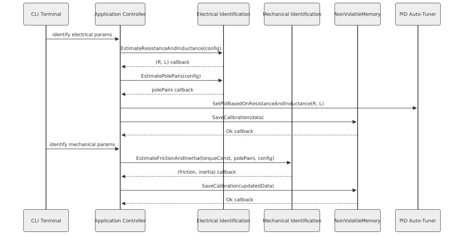
The commissioning data flow (run once at startup or on command):
Observer and Callback Patterns
The system uses two complementary asynchronous communication
patterns, both supplied by infra/embedded-infra-lib:
- Zero-allocation closures (from
embedded-infra-lib) — used for one-shot or single-subscriber callbacks. All service operations (NVM, identification, alignment) deliver their results through this mechanism. - Observer/Subject pattern (from
embedded-infra-lib) — a type-safe, heap-free mechanism where a subject notifies multiple observers. The simulator’s motor model is a subject; views and loggers attach as observers. No raw event buses or dynamic dispatch lists are used.
These patterns eliminate polling, decouple producers from consumers, and allow the application to remain single-threaded and non-blocking.
Cross-Cutting Concerns
| Concern | Policy / Approach |
|---|---|
| Memory | Absolutely no heap on the embedded target. All objects are
statically or stack-allocated. Bounded containers from
embedded-infra-lib replace STL heap-based containers.
Host-side tools and tests may use the standard heap freely. |
| Real-time determinism | The FOC Calculate() path contains no virtual dispatch,
no blocking calls, and no unpredictable branches. The outer loops run at
lower-priority interrupts on a deterministic prescale ratio. |
| Unit safety | All physical quantities use typed unit aliases (Ampere,
Radians, Volts, RadiansPerSecond,
…) from embedded-infra-lib. Raw floating-point with no unit
context is not used for motor quantities. |
| Compiler optimisation | Embedded builds compile all of e-foc with one option set: the
configuration’s level plus
-ffast-math -fno-finite-math-only. No per-function pragmas;
they block inlining. Debug builds use -Og for
debuggability. |
| Error handling | No C++ exceptions. Synchronous errors use std::optional
(absent = error). Asynchronous errors are delivered as typed status
codes in callbacks. |
| Portability | The control core has no knowledge of the underlying MCU. Portability to a new board is achieved by implementing a platform factory for that board and providing the PAL concrete implementations. |
| Testability | All modules depend on abstract interfaces, enabling host-build unit tests with mock or stub implementations. The simulator provides closed-loop integration testing without hardware. |
Open Questions & Decisions
| # | Question / Decision | Status | Options Considered | Rationale |
|---|---|---|---|---|
| 1 | Rename source/hardware/ and extract platform
targets |
resolved | Keep current name vs rename to PAL vs full extraction | Renamed to core/platform_abstraction/ (interface +
adapters only). Platform implementations (TI, ST, Host) and application
targets moved to top-level targets/. Host-only tools moved
to top-level tools/. Core tier is now purely libraries.
source/ directory renamed to core/. |
| 2 | Multi-motor support | open | Single instantiation per motor vs shared PAL with multiple FOC controllers | Current architecture supports one motor per binary. A shared PAL
with multiple FocController instances is architecturally
feasible but not yet required. |
| 3 | Field-weakening | open | Extend FocTorque interface with flux-weakening setpoint
vs separate FocTorqueFieldWeakening interface |
Required for operation above base speed. Separate interface preferred (ISP) but not yet scoped. |
Integration Testing
Integration testing drives the real firmware as a black box over the product’s own CAN command set. Nothing inside the firmware is mocked or reached into; the suite starts a target, sends commands, and asserts on telemetry and traces.
Two targets implement scenarios, selected by tag:
- Software-in-the-loop — the firmware built for an emulated Cortex-M4, running under an emulator against a simulated three-phase motor the firmware itself owns. Only the motor, the power stage and the board protection are simulated, because there is no hardware. The motor is described per scenario and handed to the firmware at boot, and non-volatile memory is pre-seeded so a scenario starts from a chosen calibration and configuration.
- Hardware-in-the-loop — the same firmware on a real board, reached through the hardware bridge over serial and CAN.
Design detail:
documentation/design/integration-testing.md for the shared
structure, and documentation/design/software-in-the-loop.md
for the simulated target.

Integration Boundaries
| Boundary | Software-in-the-loop | Hardware-in-the-loop |
|---|---|---|
| Motor and power stage | Simulated plant, described per scenario | Real motor and inverter |
| Board protection | Simulated comparators, armed with the inverter | Real comparators |
| Non-volatile memory | Host-written image, pre-seeded or deliberately damaged | Real device |
| State machine, cascades, calibration, NVM stack, CAN server | Real firmware | Real firmware |
| Transport | CAN frames as text on the emulated UART | Bridge over serial and CAN |
Requirements Traceability
Each scenario carries the requirement identifiers it verifies as tags, alongside the tag naming the target that implements it. The traceability matrix is generated from those tags at release time by reading the feature directory, so the mapping lives with the scenarios rather than in a table here that would drift away from them.
Requirements with no scenario are verified by unit tests under the owning library, or are structural constraints discharged by design review; the generated matrix reports both.